Installing the PIN Pad Blanking Plate
To install PIN Pad Blanking Plate, follow these steps:
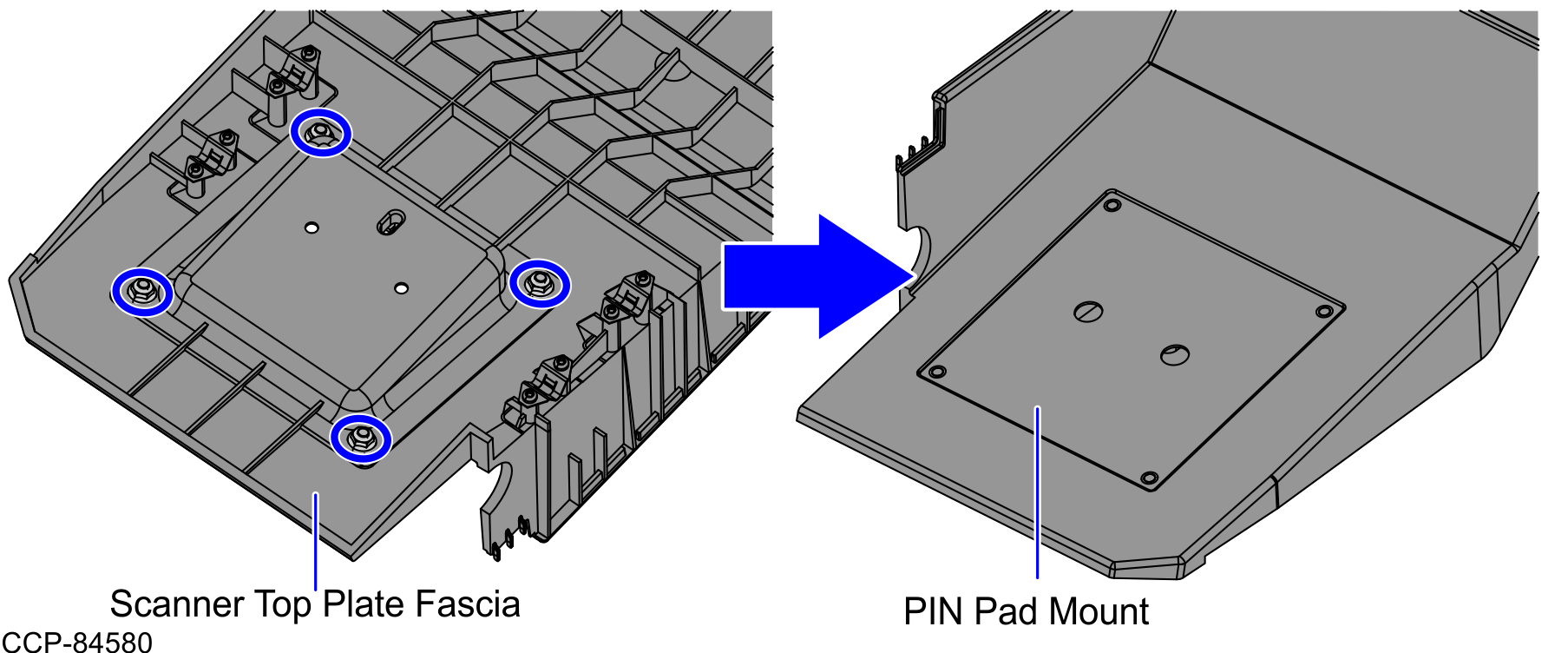
Remove the Front PIN Pad Mount. For more information, refer to Removing the Front PIN Pad Mount.
- Align and insert the studs of the Blanking Plate into the corresponding holes on the Scanner Top Plate (Plastic), as shown in the image below.
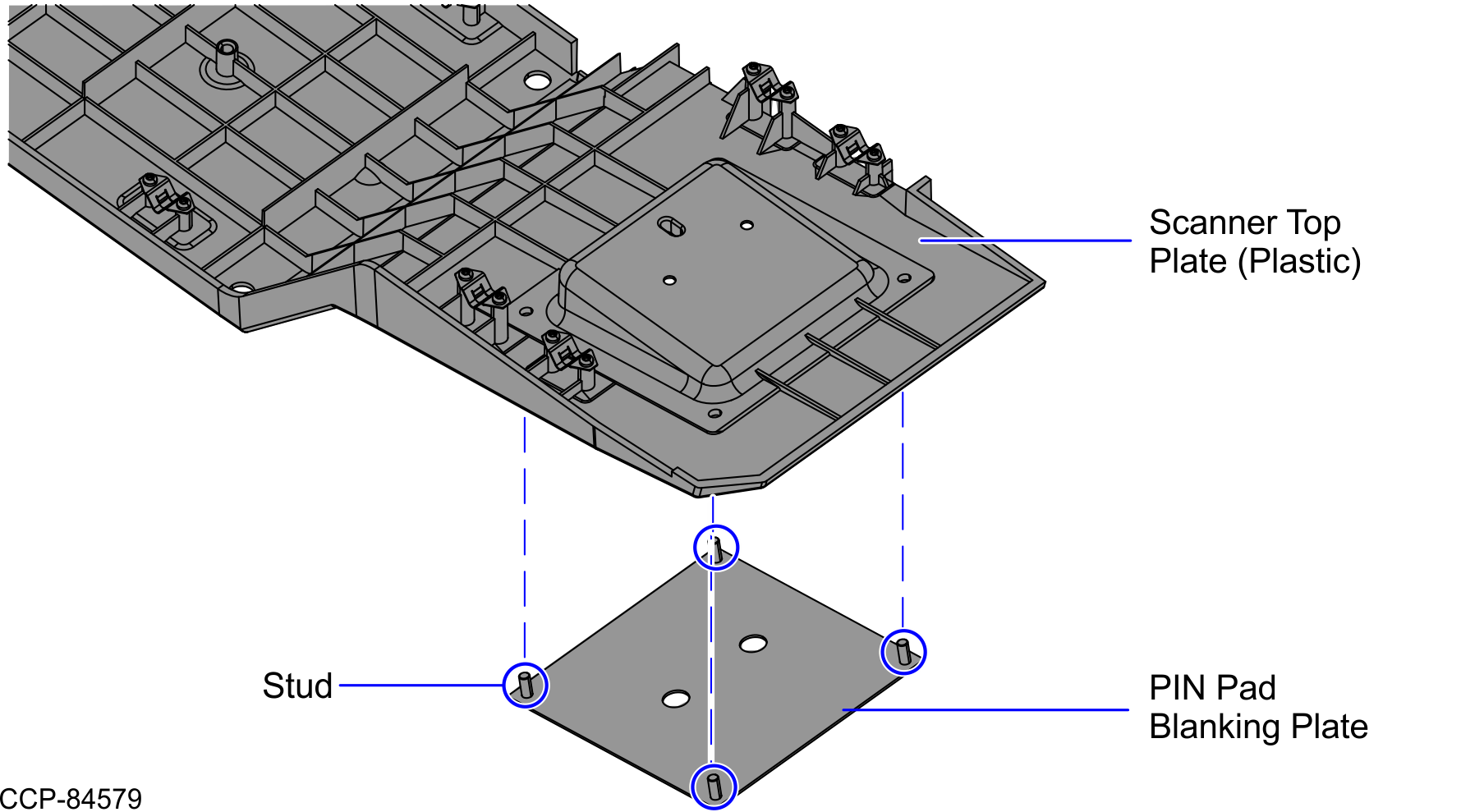
- Secure the Blanking Plate using four (4) nuts from the rear of the Scanner Top Plate (Plastic).
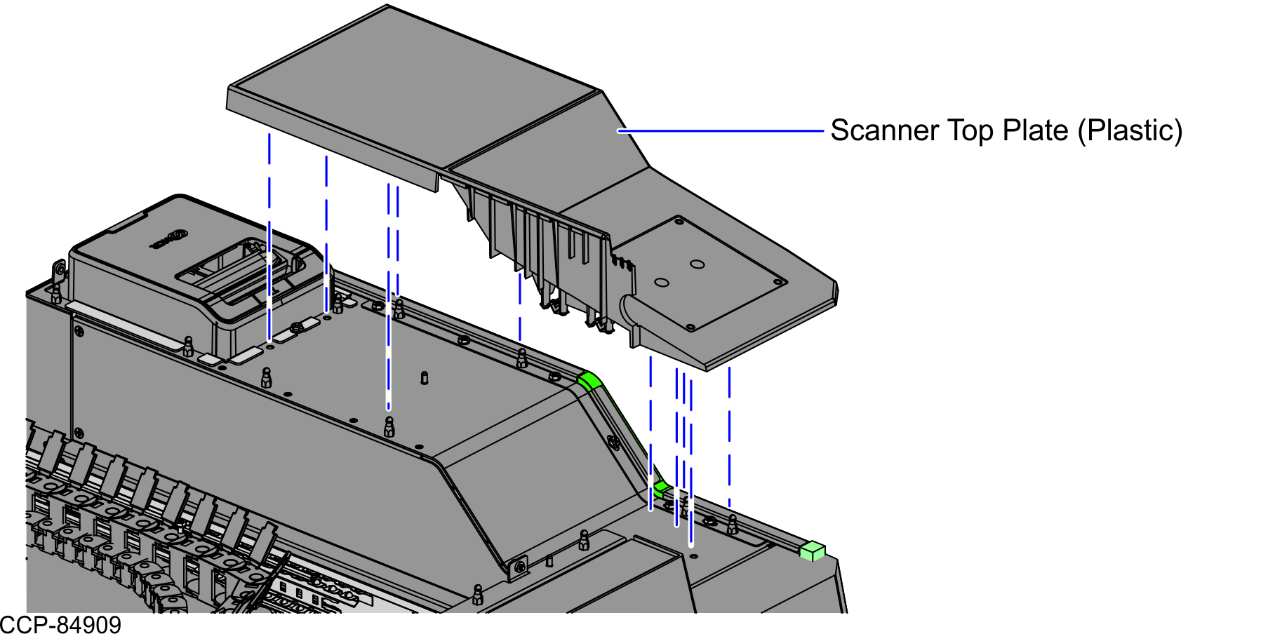
- Install the Scanner Top Plate (Plastic) from the Core (Cabinet), as shown in the image below.
- Install two (2) screws on the Blanking Plate, as shown in the image below.
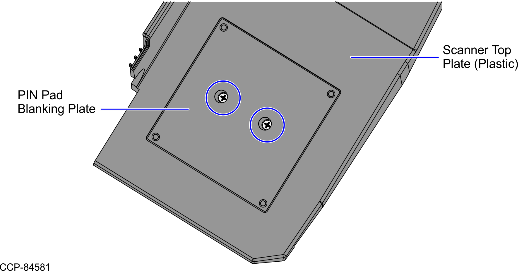
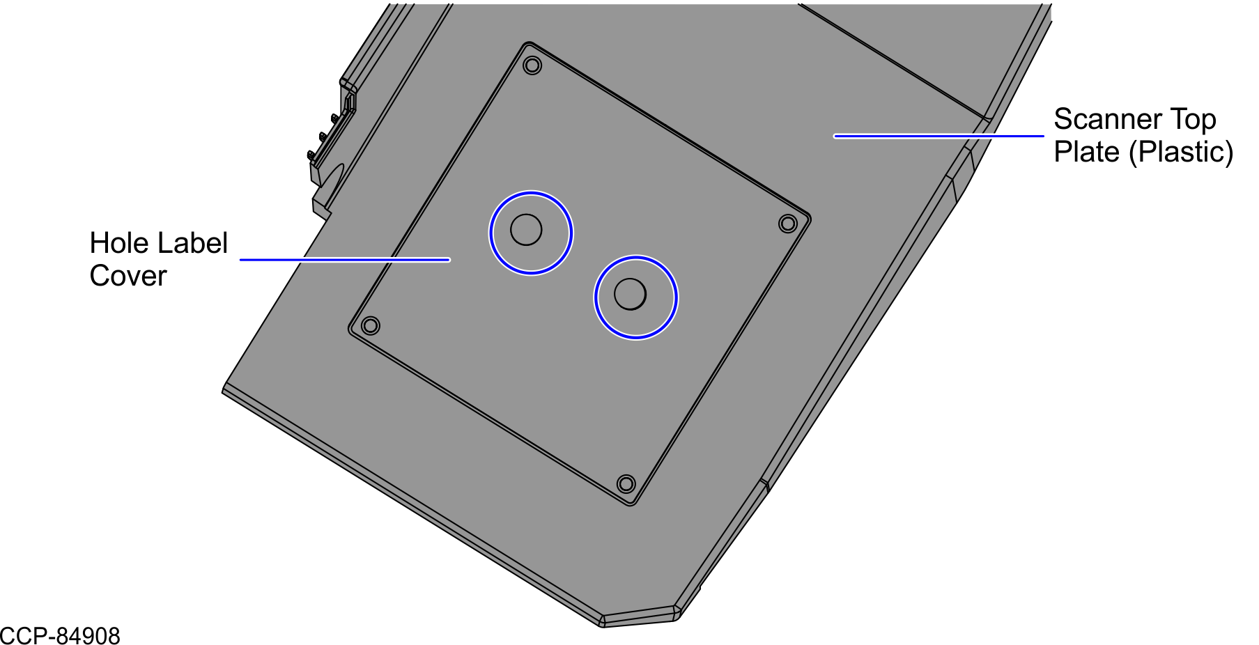
- Cover the two (2) holes on the Blanking Plate with two (2) Hole Cover labels, as shown in the image below.
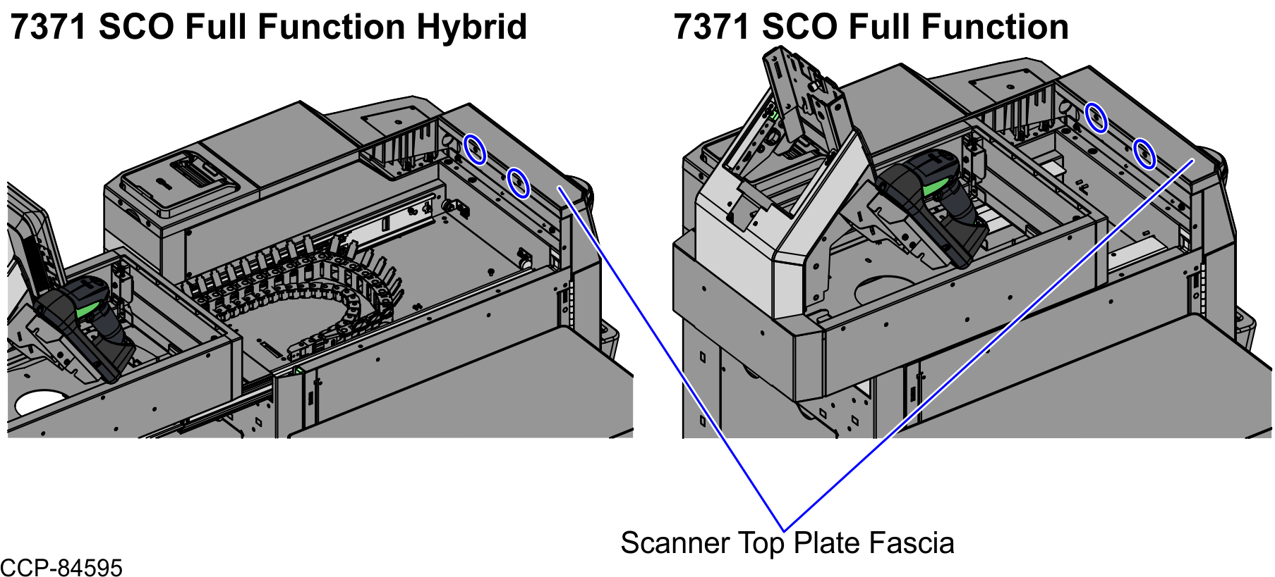
- Install the Scanner Top Plate Fascia on the Core (Cabinet) and then secure using two (2) screws.
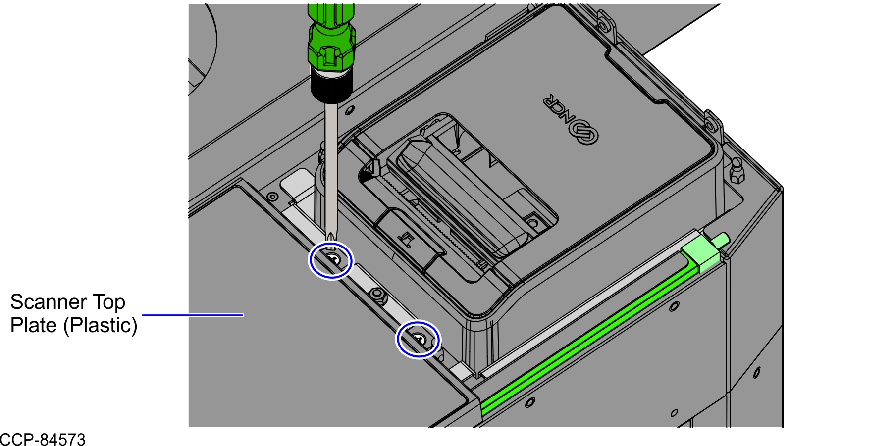
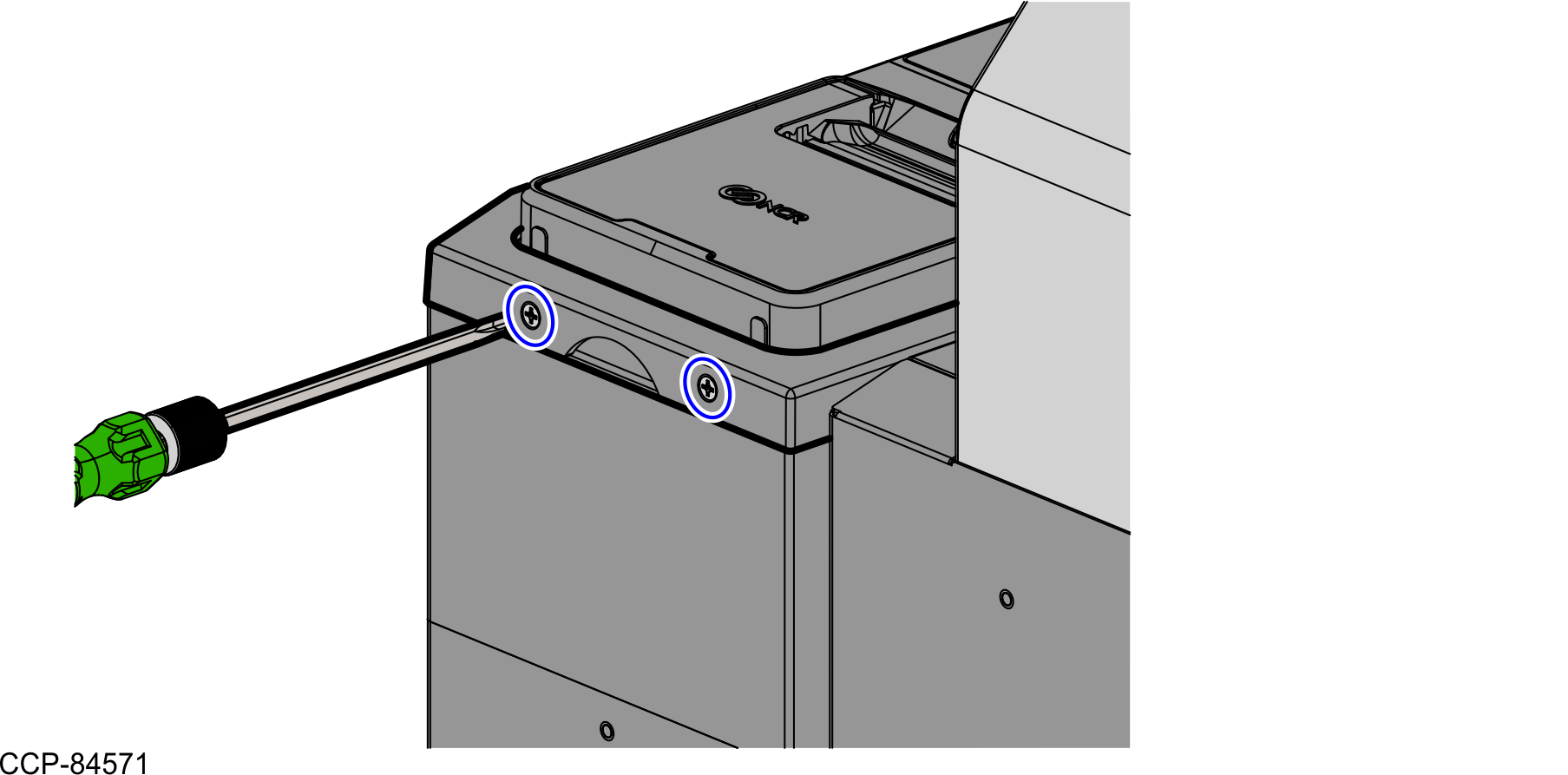
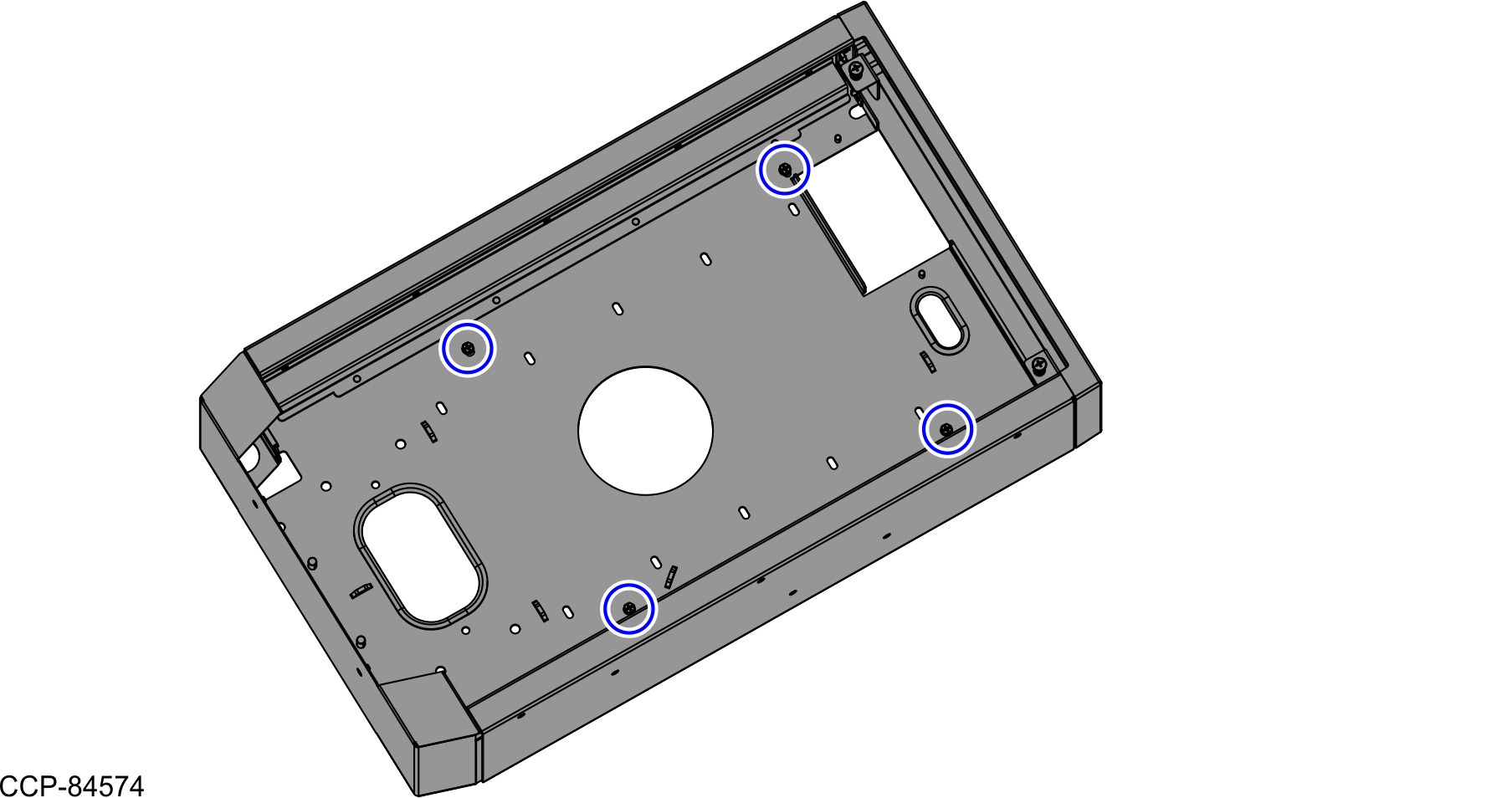
- Secure the Scanner Top Plate (Plastic) using two (2) screws to the Core (Cabinet), as shown in the image below.
- Install the Printer Cover by doing the following:
- Hold the Finger Access hole to attach the Printer Cover on the Receipt Printer.
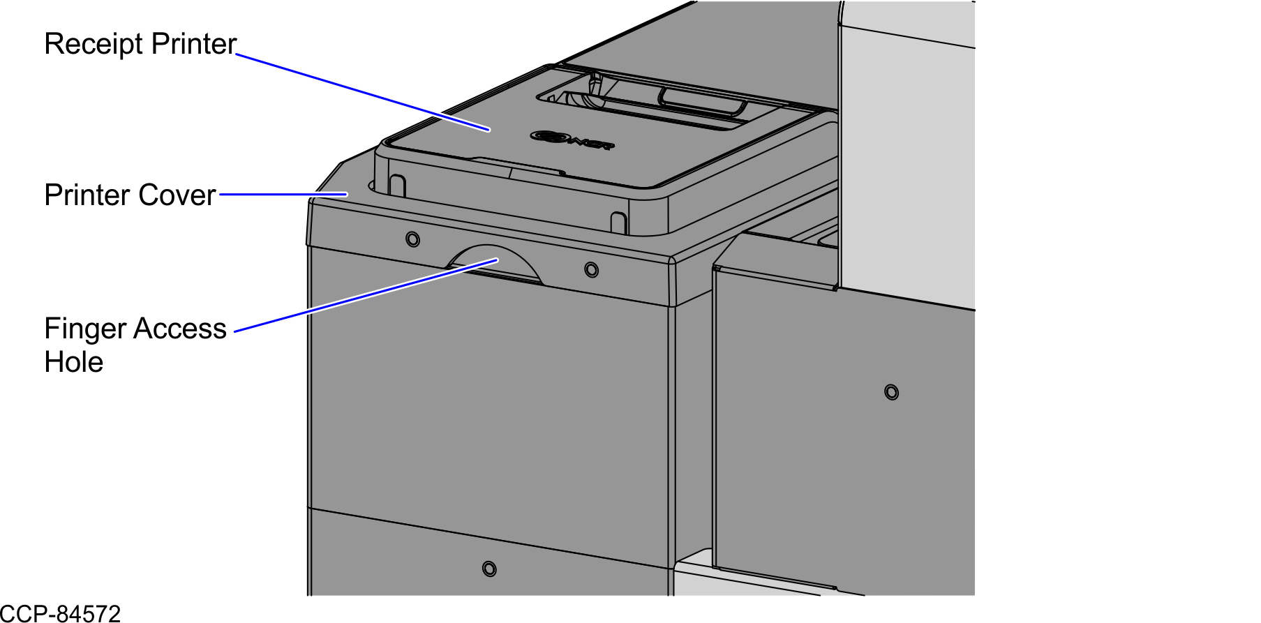
- Secure the Printer Cover to the Core (Cabinet) using two (2) screws, as shown in the image below.
- Hold the Finger Access hole to attach the Printer Cover on the Receipt Printer.
- Depending on the unit, do either of the following:
- If the unit is a SCO Full Function Hybrid, do the follow these steps:
- Push the Tower assembly back into the Scanner Bucket.
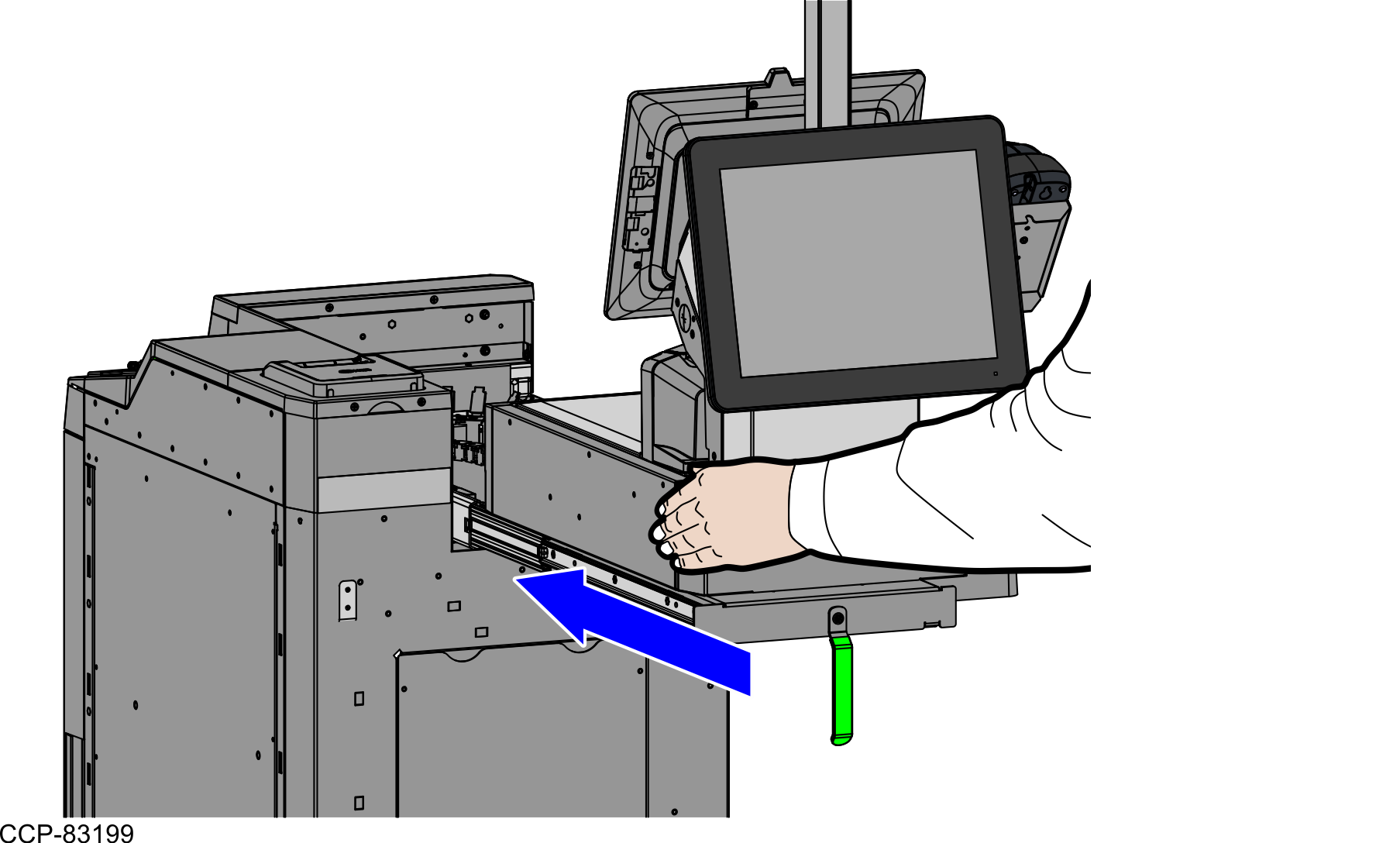
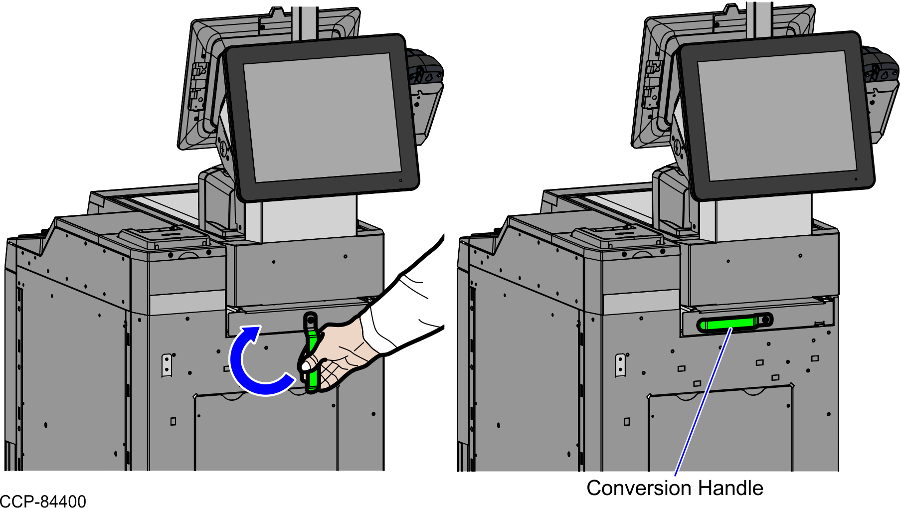
- Turn the Conversion Handle to the left to lock the Tower assembly into the Scanner Bucket, as shown in the image below.
- Push the Tower assembly back into the Scanner Bucket.
- If the unit is a SCO Full Function Fixed, follow these steps:
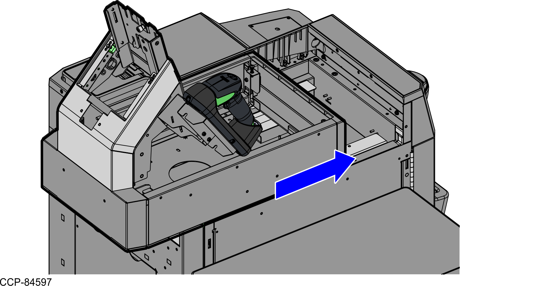
- Push the Tower Module assembly to the front of the unit, as shown in the image below.
- Secure the Scanner Bucket using four (4) screws, as shown in the image below.
- Install the Scanner/Scale. For more information, refer to Installing the 7895 Scanner/Scale.
- Push the Tower Module assembly to the front of the unit, as shown in the image below.
- If the unit is a SCO Full Function Hybrid, do the follow these steps: