Removing the Front PIN Pad Mount
To remove the Front PIN Pad Mount from the Scanner Top Plate (Plastic), follow these steps:
- Remove the PIN Pad device. Depending on the PIN Pad device, refer to the procedure in any of the following Kit Instructions:
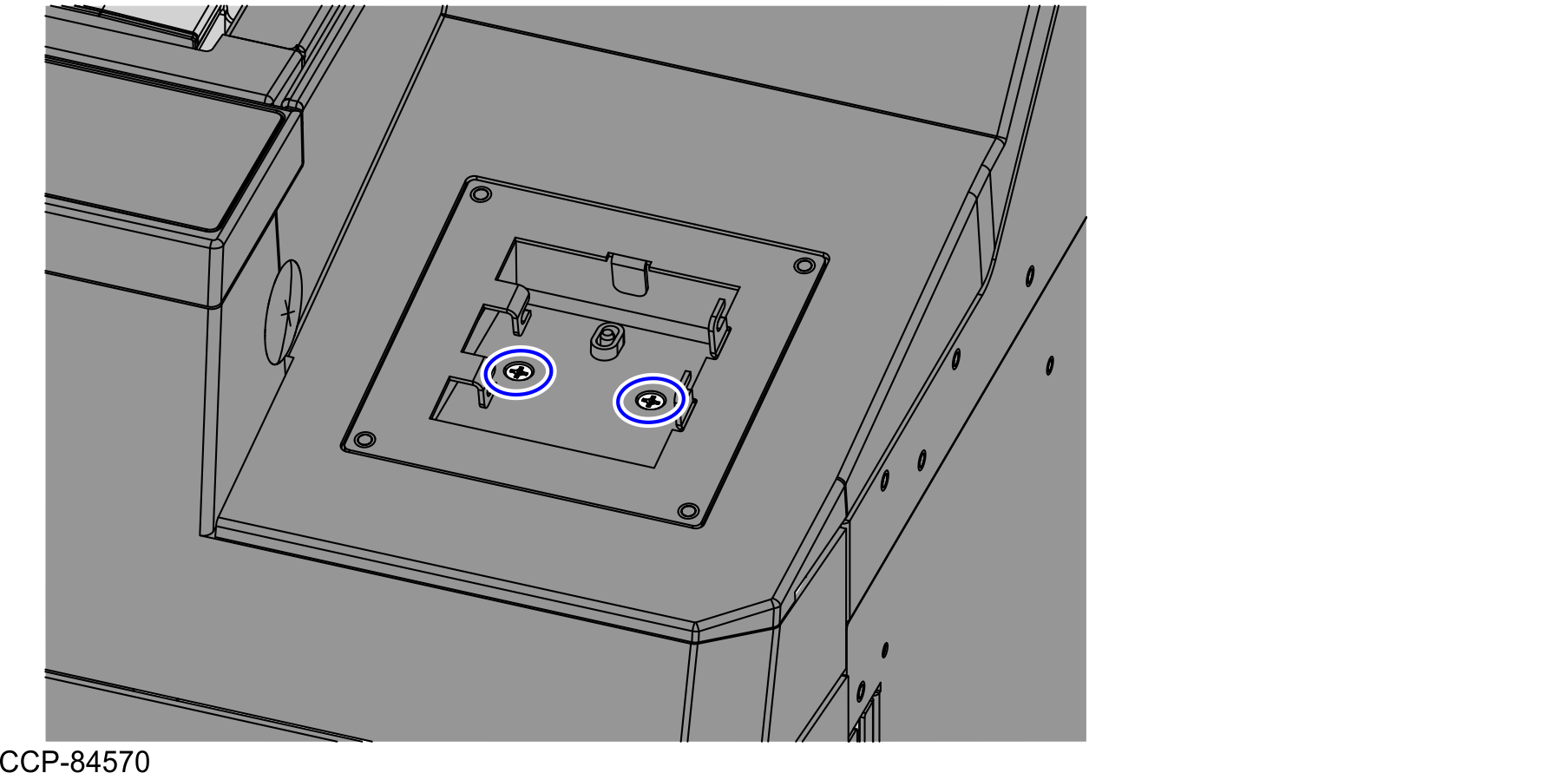
- Remove two (2) screws from the PIN Pad Mount Base Plate, as shown in the image below.Note
Set aside the removed screws. These will be reused when installing PIN Pad Blanking Plate.
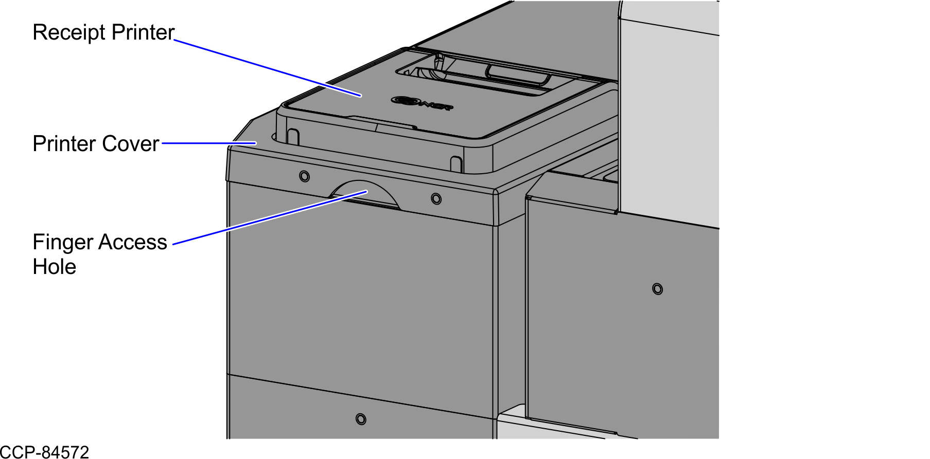
- Remove the Printer Cover by doing the following:
- Remove two (2) screws from the rear of the Printer Cover, as shown in the image below.
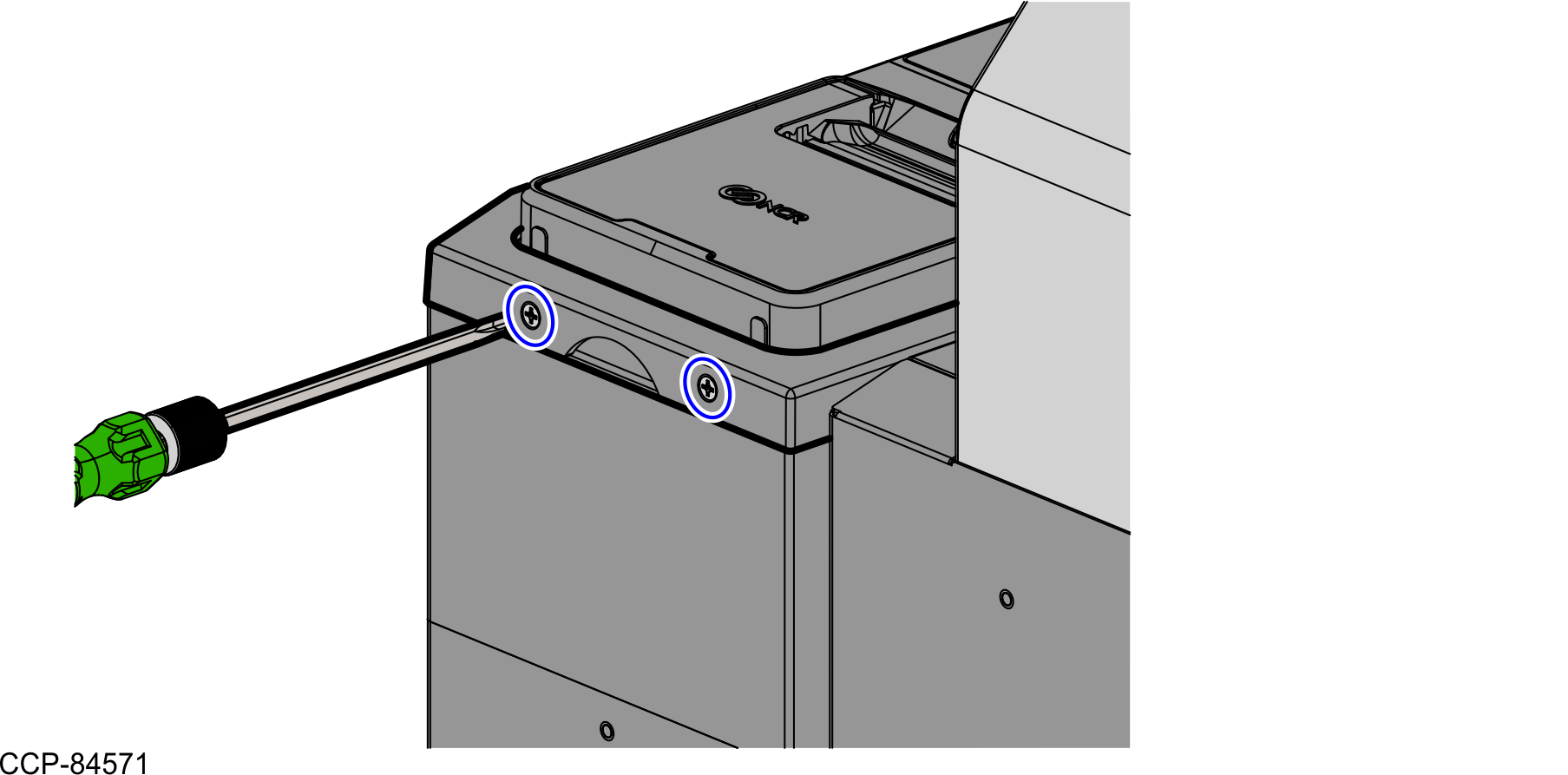
Hold the Finger Access hole to detach and lift the Printer Cover.
- Remove two (2) screws from the rear of the Printer Cover, as shown in the image below.
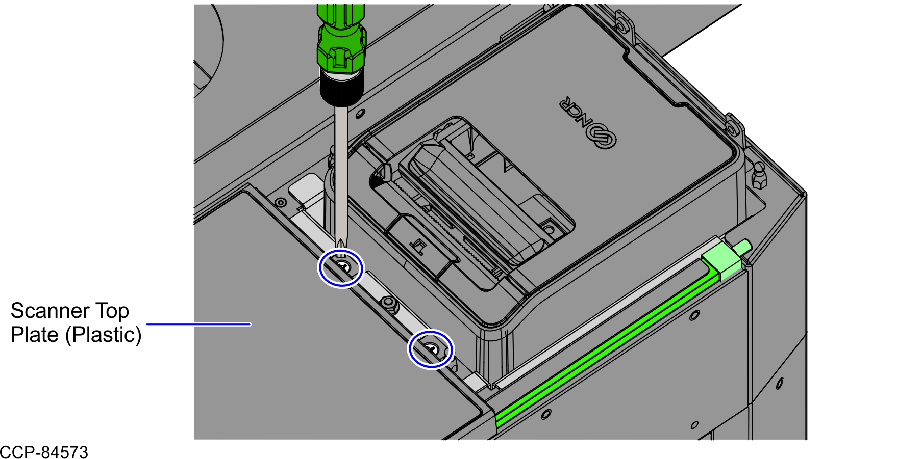
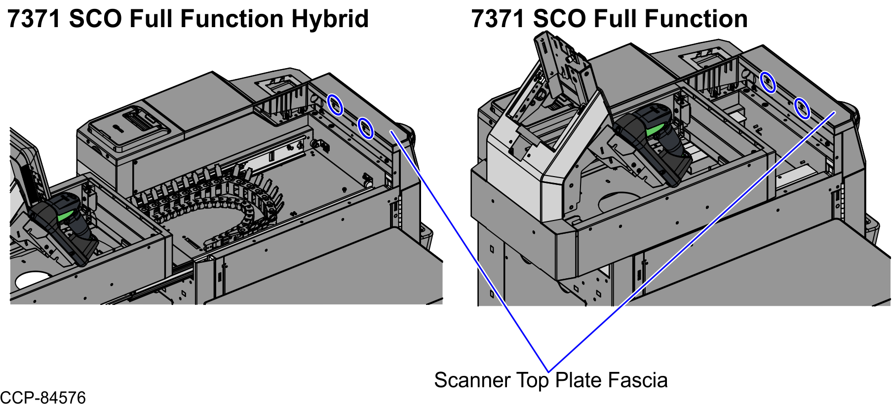
- Remove two (2) screws at the rear of the Scanner Top Plate (Plastic), as shown in the image below.
- Depending on the unit, do either of the following:
- If the unit is a SCO Full Function Hybrid, rack out the Tower Module assembly.
- Turn the Conversion Handle down to 90 degrees to unlock the Tower assembly, as shown in the image below.
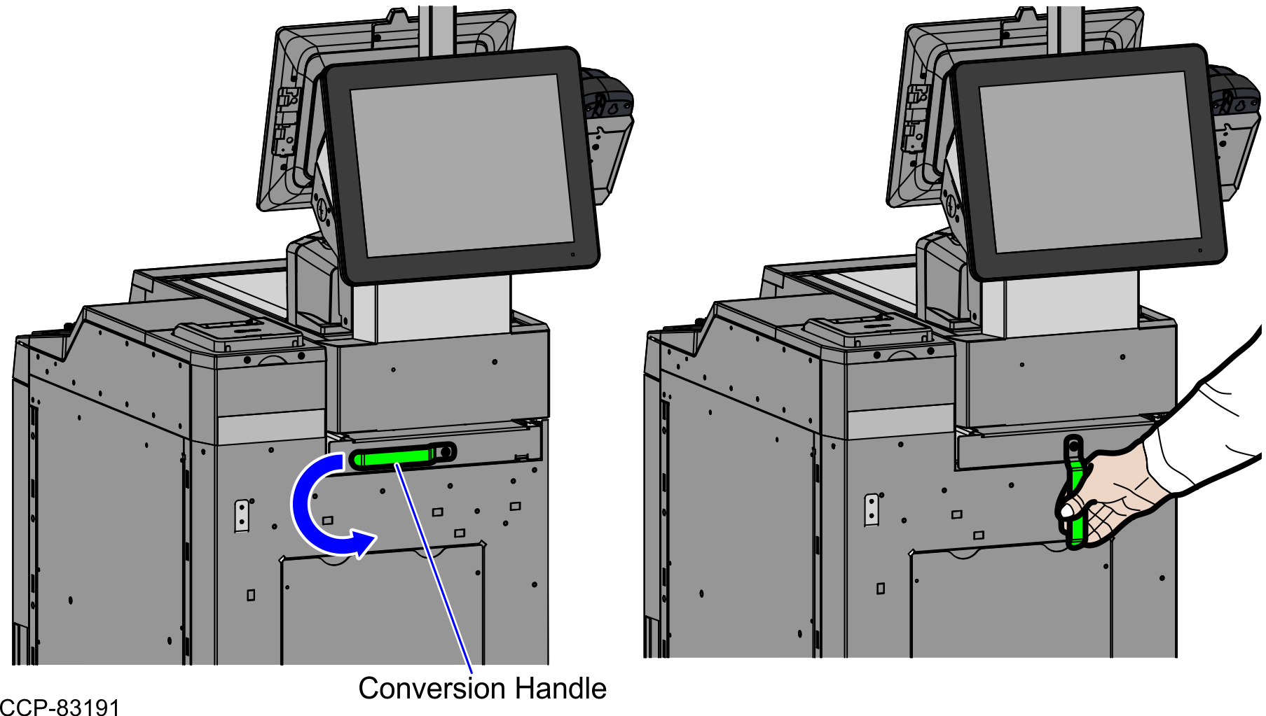
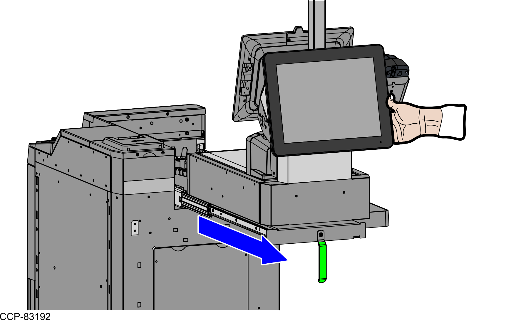
- Pull the Tower assembly forward. Ensure that the Tower assembly is fully racked out.
- Turn the Conversion Handle down to 90 degrees to unlock the Tower assembly, as shown in the image below.
- If the unit is a SCO Full Function Fixed, do the following:
- Remove the Scanner/Scale. For more information, refer to Removing the 7895 Scanner/Scale from Full Function Configuration.
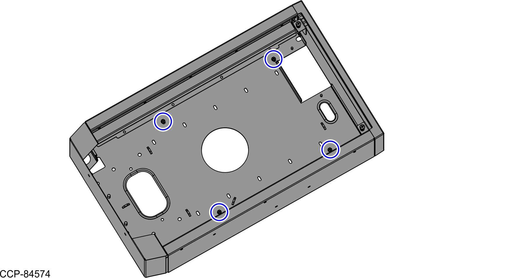
- Remove four (4) screws from the bottom of the Scanner Bucket, as shown in the image below.
- Slightly push the Tower Module assembly to the back, as shown in the image below.
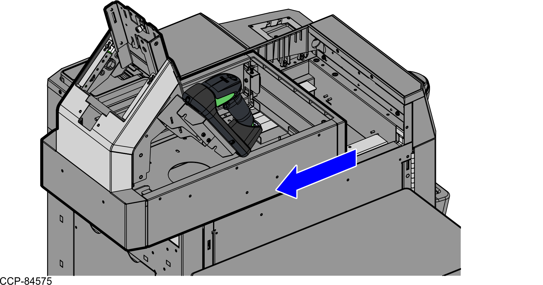
- If the unit is a SCO Full Function Hybrid, rack out the Tower Module assembly.
- Remove two (2) screws to detach the Scanner Top Plate Fascia.
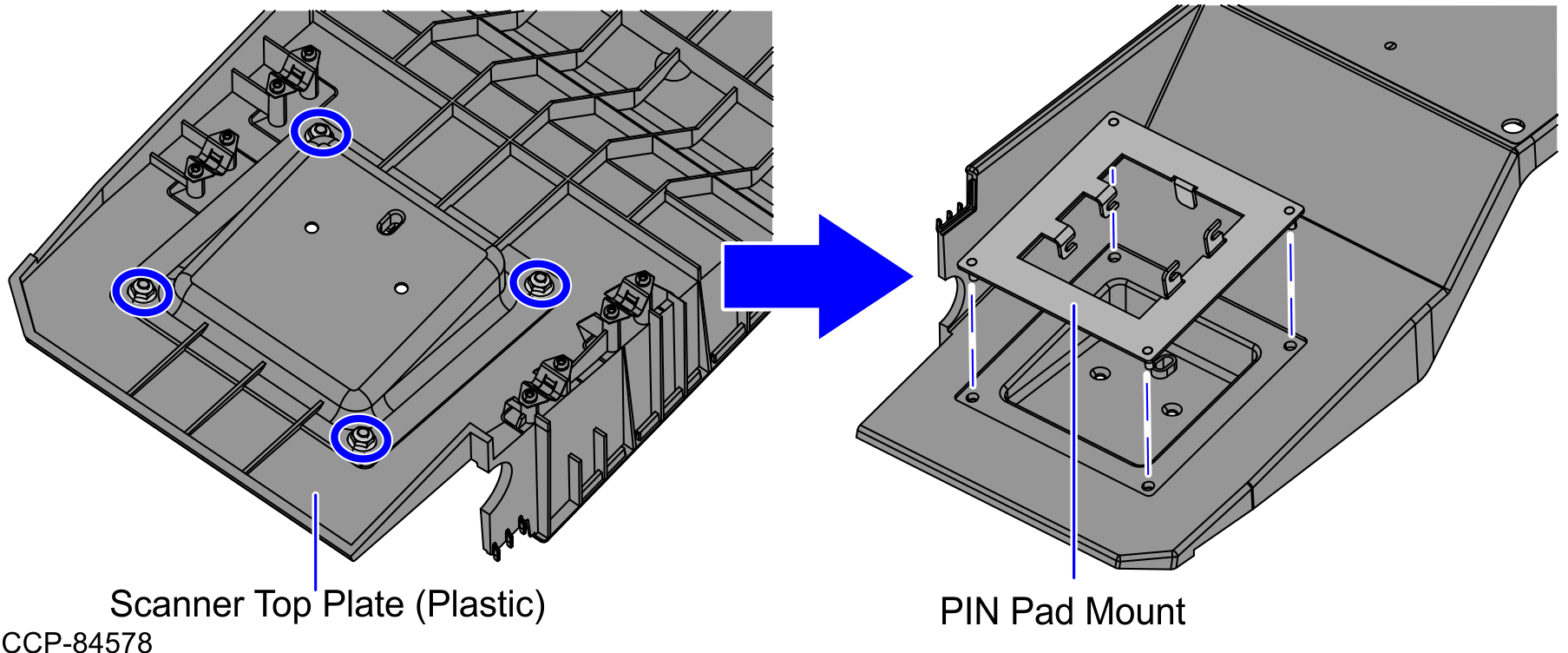
- Lift and remove the Scanner Top Plate (Plastic) from the Core (Cabinet), as shown in the image below.
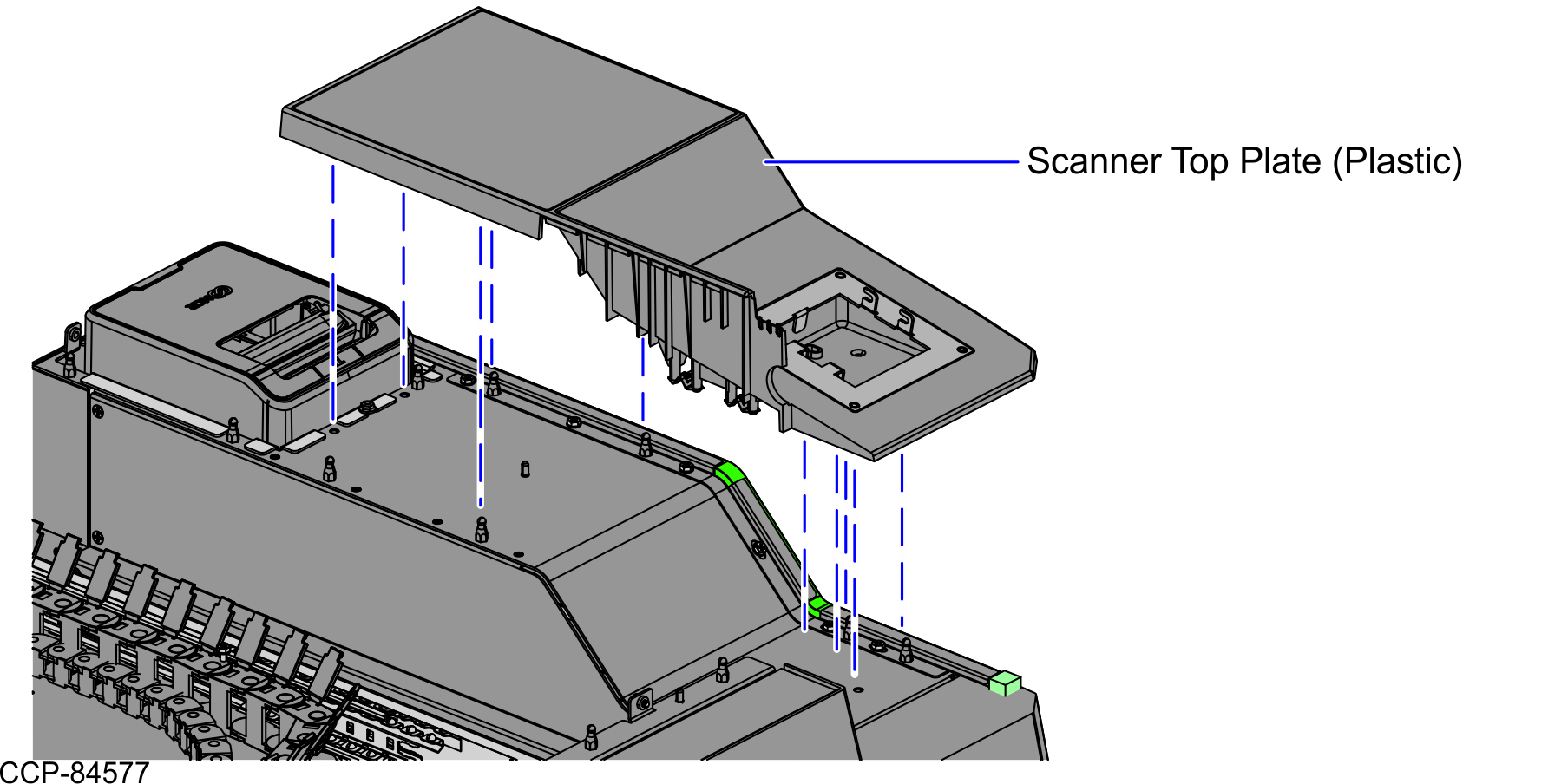
- From the rear of the Scanner Top Plate (Plastic), remove four (4) nuts to detach the PIN Pad Mount.