9700-0060-7746 / 9700-0061-7746 7746 Battery Assembly
This kit provides a stand top cover with battery for the NCR PX10/PX15 POS (7746).
|
PID |
Description |
|---|---|
|
9700-0060-7746 |
7746 Battery Assembly |
|
9700-0061-7746 |
7746 Battery Assembly, Orderman |
Note: The Battery comes attached to the Top Cover.
Battery Driver
Windows OS
1.Ensure you have the latest Windows BIOS from NCR.com. You must have version 1.0.9.1 or higher for proper battery operation.
2.Ensure you have the latest Windows PX10 battery driver package from NCR.com: https://www5.ncr.com/support/support_drivers_patches_radiant.asp?Class=Hospitality/PX10_recent_display
For proper battery operation, you must have battery driver package v1.0.1.0 or higher.
3.Install the battery.
4.Re-start the unit. The unit must be rebooted before the battery will work.
Android OS
1.Ensure you have the latest Android BIOS from NCR.com. You must have version 2.0.9.1 or higher for proper battery operation.
2.Work with your NCR Account Manager or Professional Services Partner to ensure you have the latest NCR Android operating system image integrated into your system. Battery drivers are built into the NCR Android image. For proper battery operation, you must have NCR Android image v1.6.0 or higher (engineering ROM530441/497-0523921 or user ROM530442/497-0523922).
3.Install the battery.
4.Re-start the unit. The unit must be rebooted before the battery will work.
Note: Windows and Android BIOS images are different. Windows BIOS versions start with a “1” (1.x.x.x), while Android BIOS versions start with a “2” (2.x.x.x). Failure to use the appropriate BIOS image will result in unreliable operation.
Installation Procedure
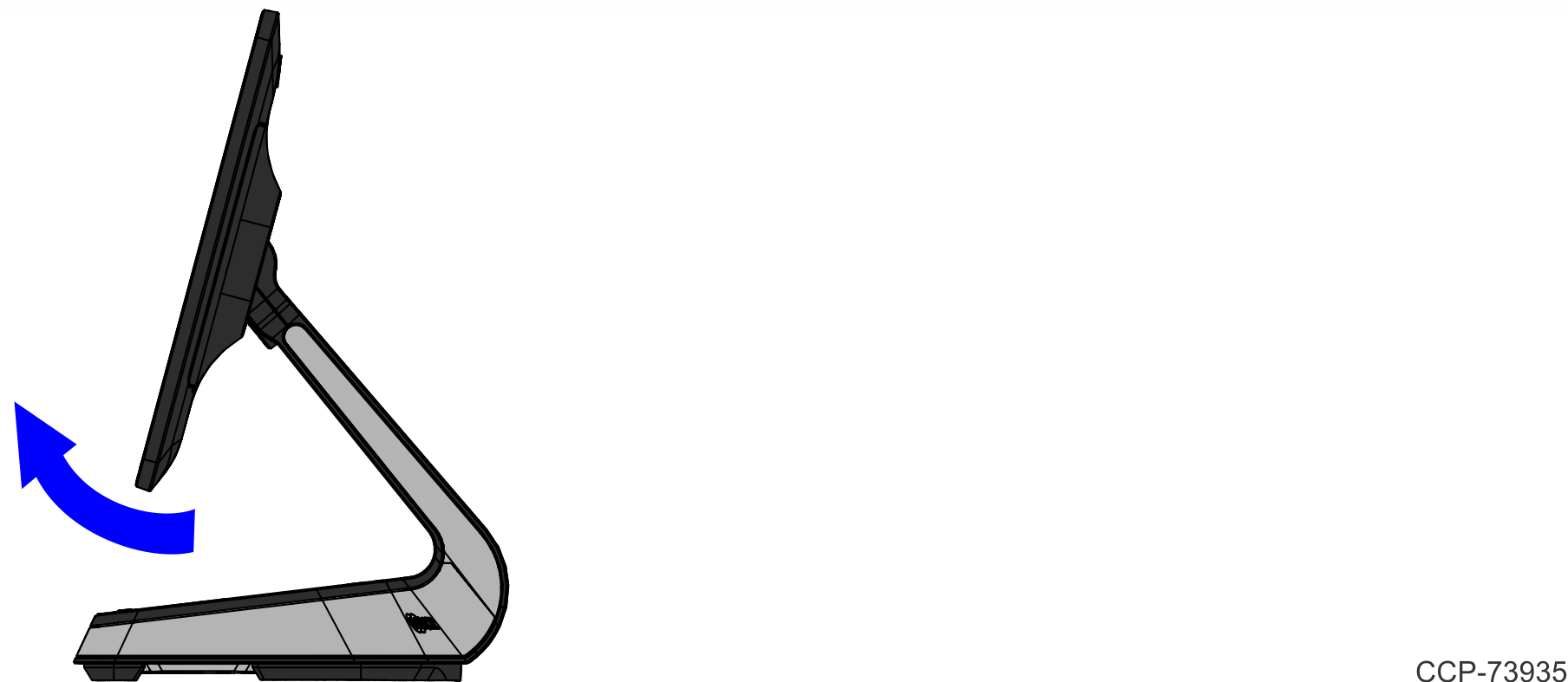
1.Pivot the display toward the back.
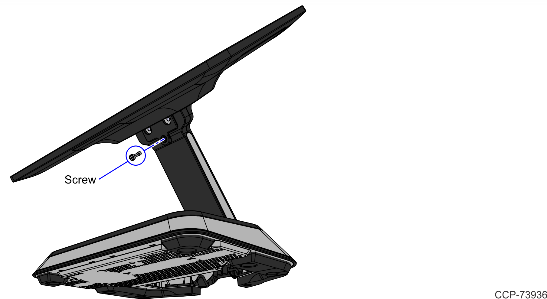
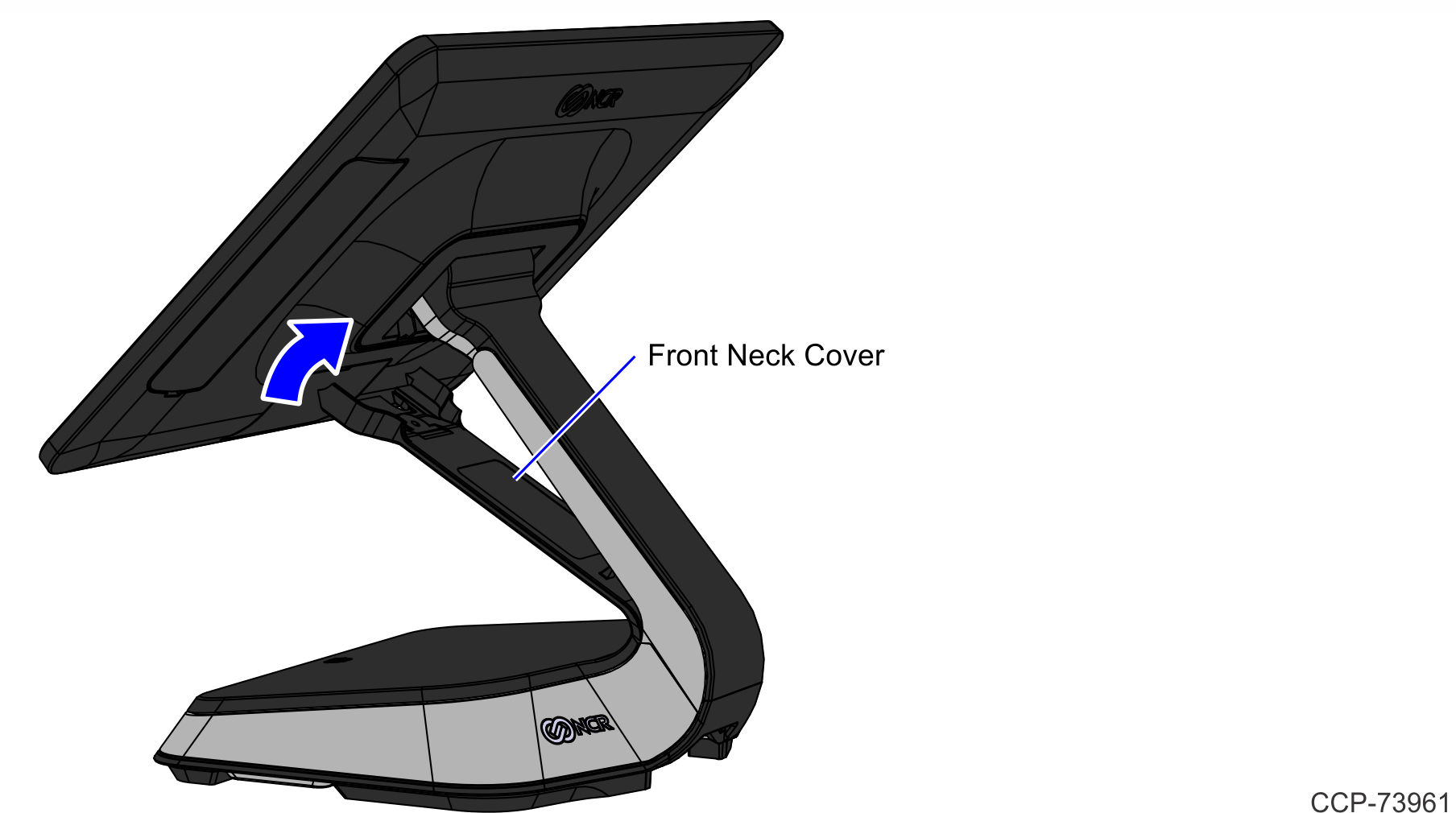
2.Remove the screw (1) that secures the Front Neck Cover to the neck.
Note: Use only a screwdriver with a #1 Philips bit to avoid stripping the screw head.
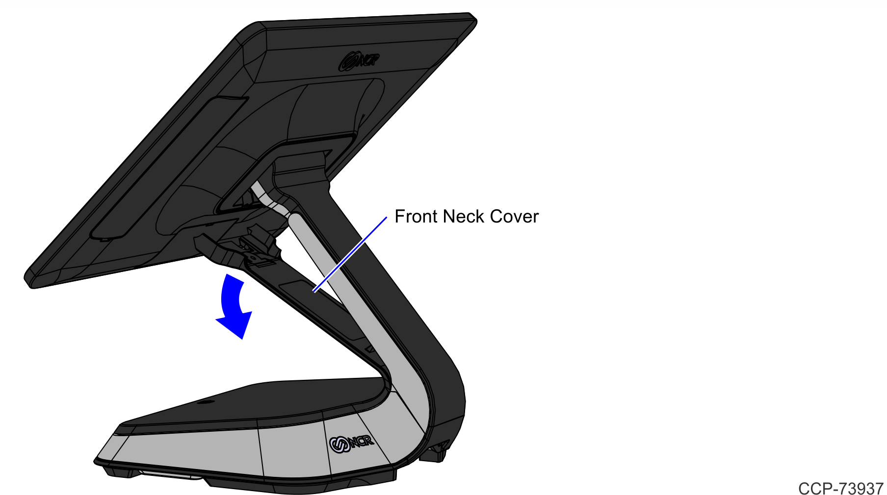
3.Pivot the Front Neck Cover away from the terminal.
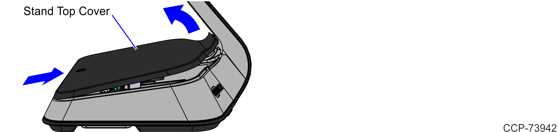
4.Slightly push the front side of the Stand Top Cover, and then pivot the Cover open.
5.Install the Top Cover with Battery Assembly kit.
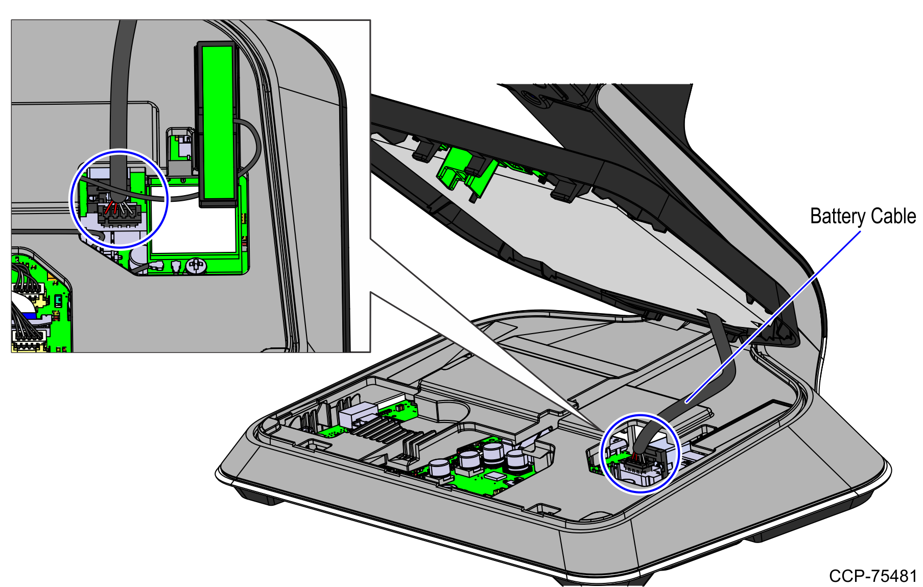
a.Connect the Battery Cable to the Motherboard.
Note: The Battery Cable may have to be peeled off the Battery surface for easy connection.
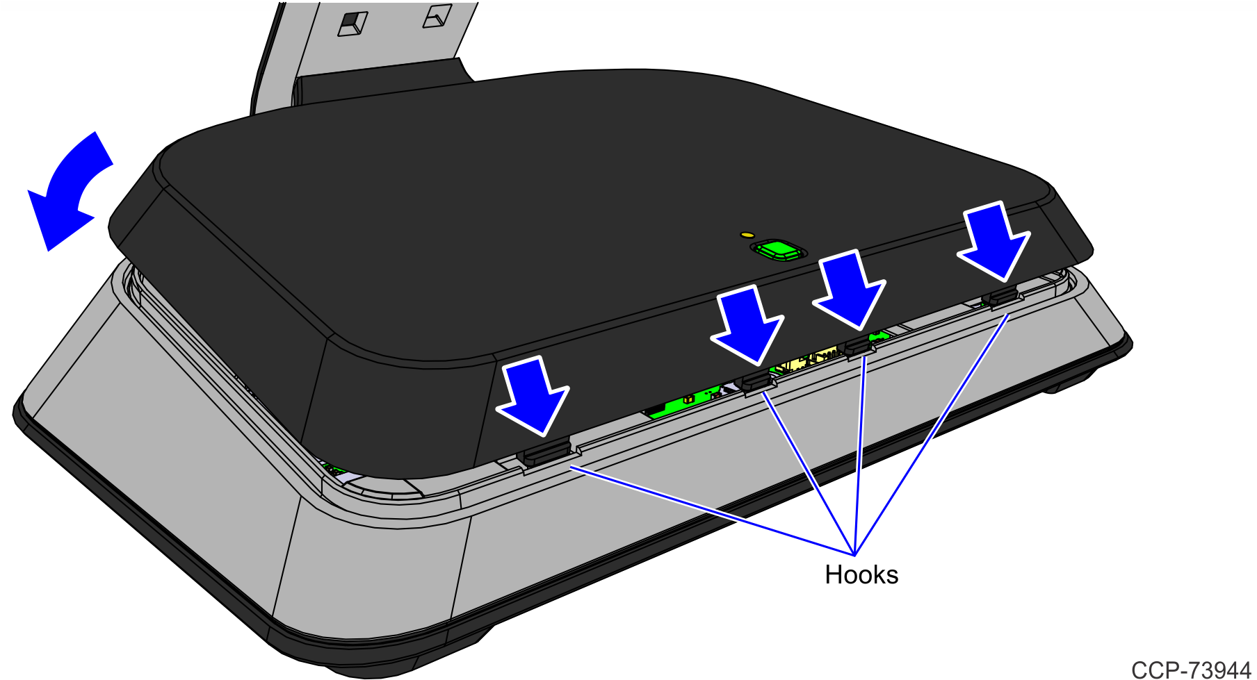
b.Hook the Stand Top Cover into the stand, and then snap into place.
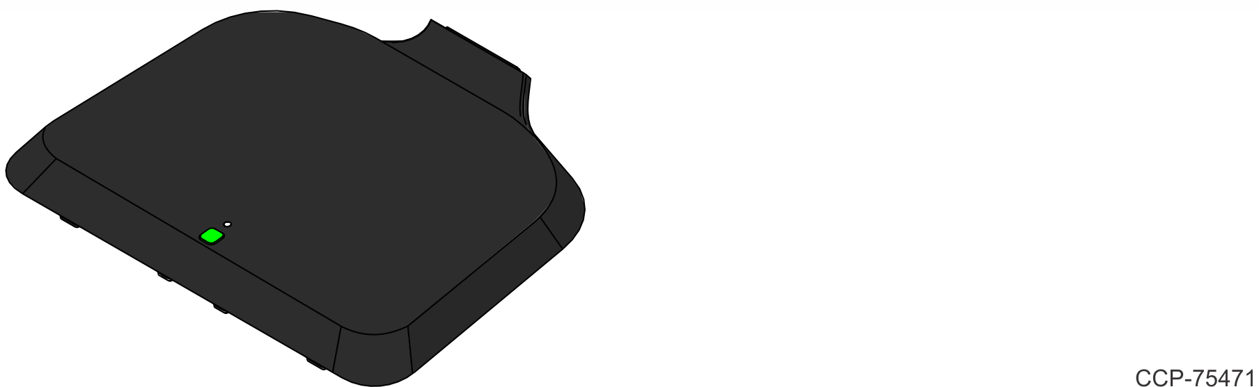
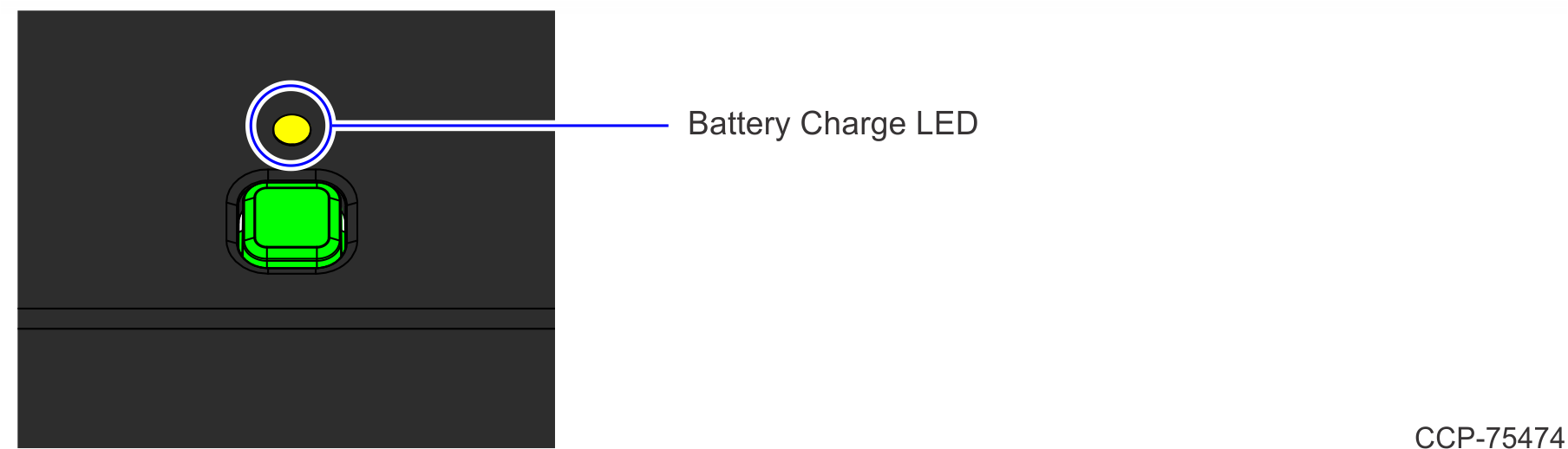
Note: After the Stand Top Cover is installed, check if the Battery Charge LED is flush with the top surface of the Cover. If the LED Lightpipe is protruding, push it flush with the Cover.
6.Attach the Front Neck Cover to the terminal.
7.Secure the Front Neck Cover to the neck with a screw (1).
System States
When the unit is connected to AC Power
•The system runs at maximum performance. However, the performance decreases at high system temperatures.
•The Power LED is always ON.
|
LED Color |
Status |
|---|---|
|
Off |
System is OFF. |
|
Solid Green |
System is ON. |
|
Solid Blue |
System is on STANDBY or SLEEP state. |
|
Solid Orange |
System is in SOFT OFF or HIBERNATE state. |
•If the battery is installed,
•
|
LED Color |
Status |
|---|---|
|
Off |
Battery is not installed or no AC power source and battery is fully depleted |
|
Solid Green |
100% charged with AC power source or above 30% charged without AC power source |
|
Slow Green |
Charging, with charge level between 30% and 100% |
|
Solid Orange |
No AC power source, with charge level between 10% and 30% |
|
Slow Orange |
Charging, with charge level between 10% and 30% |
|
Solid Red |
No AC power source, with charge level between 0% and 10% |
|
Slow Red |
Charging, with charge level between 0% and 10% |
|
Fast Red |
Battery needs to be replaced |
•The battery is charged if it is not at maximum capacity.
•The battery is not charged if its temperature is below 0°C (32°F) or above 45°C (113°F). This is to maximize the battery lifespan.
When the unit is running on Battery Power only
•The system runs at reduced performance to extend the system battery life.
•If the system temperature drops below 10°C (50°F), the system performance is further reduced.
•The Power LED turns green when ON and blue when SLEEPING, but it turns completely OFF if the unit is shut down. The power button still functions even if the LED is OFF.
•
|
LED Color |
Status |
|---|---|
|
Off |
Battery is not installed or no AC power source and battery is fully depleted |
|
Solid Green |
100% charged with AC power source or above 30% charged without AC power source |
|
Slow Green |
Charging, with charge level between 30% and 100% |
|
Solid Orange |
No AC power source, with charge level between 10% and 30% |
|
Slow Orange |
Charging, with charge level between 10% and 30% |
|
Solid Red |
No AC power source, with charge level between 0% and 10% |
|
Slow Red |
Charging, with charge level between 0% and 10% |
|
Fast Red |
Battery needs to be replaced |
When the Customer Display is connected to USB-C port
The customer display functions when:
•It is connected before the system boots on AC power.
•It is connected to a system that is running on AC power.
Note: If the system has a battery and is removed from AC power, the customer display remains ON.
The customer display does not turn on when:
•It is connected to a unit that is booted on battery power.
•It is connected to a unit that is running on battery power.
•It is reconnected to AC power.