Installing the Receipt Printer
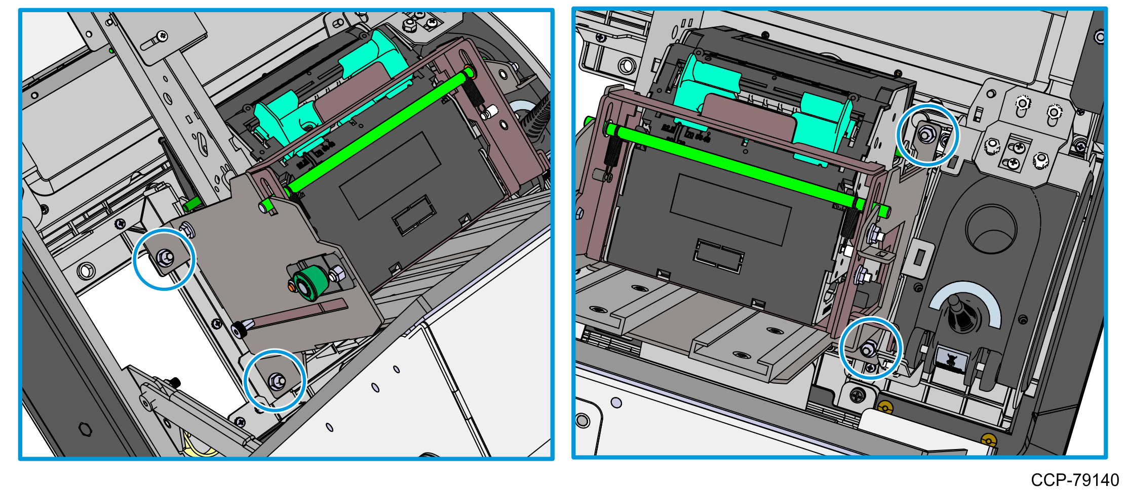
- Mount the printer assembly onto its four mounting studs on the back of the display, and secure it with four M4 nuts.
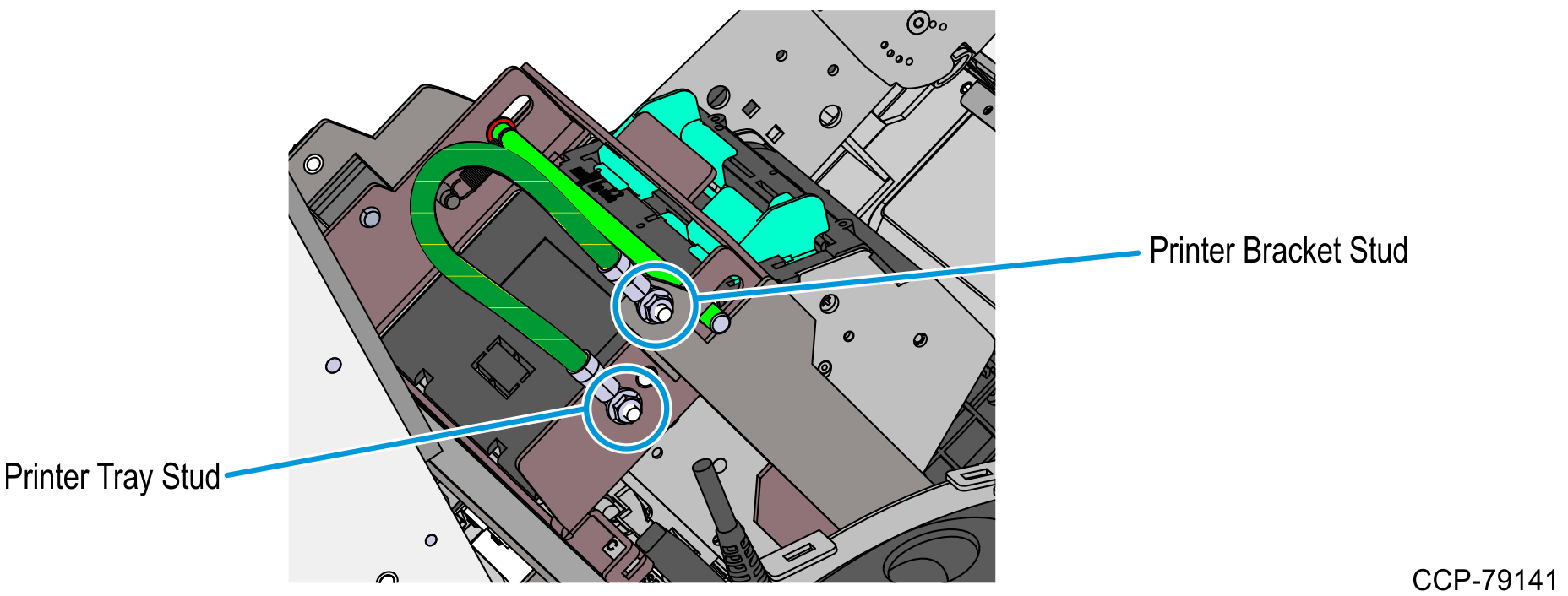
- Using two M4 serrated nuts, connect one end of the 6-inch Ground Cable to the stud on the Printer Bracket and the other end to the stud on the Printer Tray.
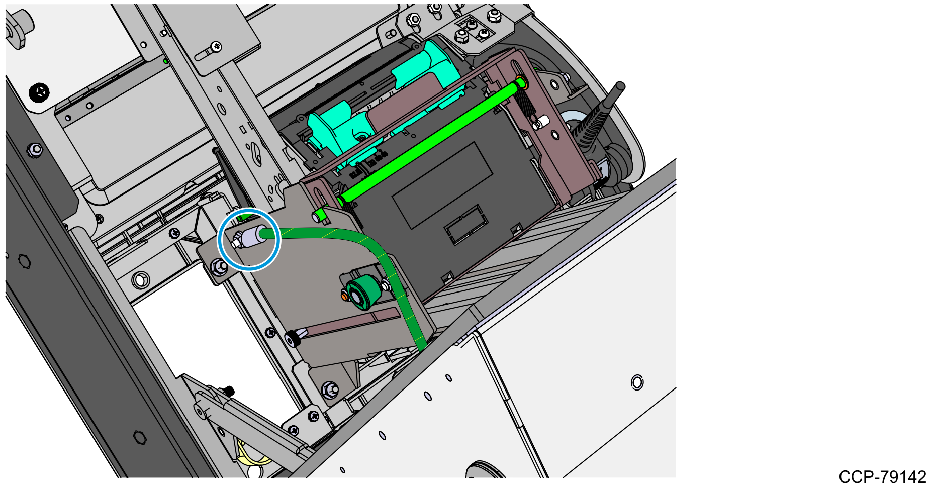
- Install the 12-inch Ground Cable.
- Using an M4 serrated nut, connect one end of the 12-inch Ground Cable to the mounting stud on the Printer Bracket.
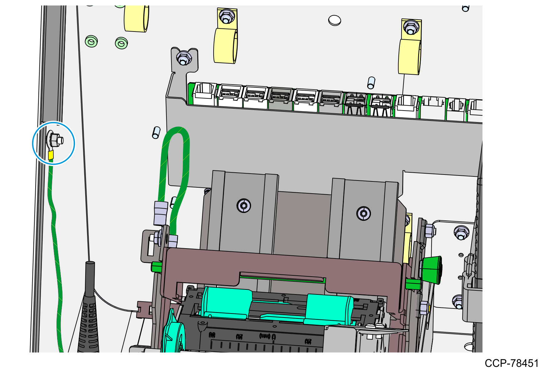
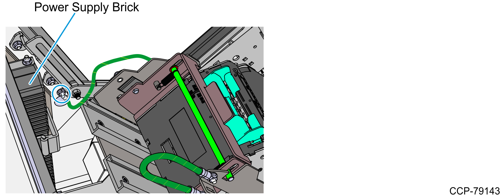
- Secure the other end of the 12-inch Ground Cable to the metal stud on the inner right wall of the bucket, right beside the Power Supply Brick.Note
There may be other ground cables attached to the same metal stud.
- Using an M4 serrated nut, connect one end of the 12-inch Ground Cable to the mounting stud on the Printer Bracket.
- Slide the printer assembly upward into service position.
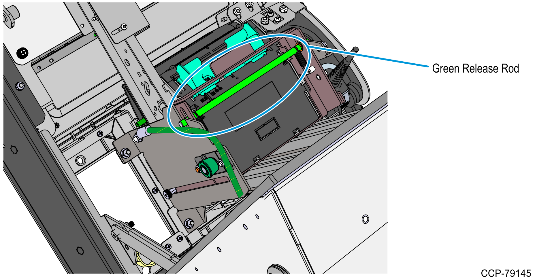
- Push the green release rod upward.
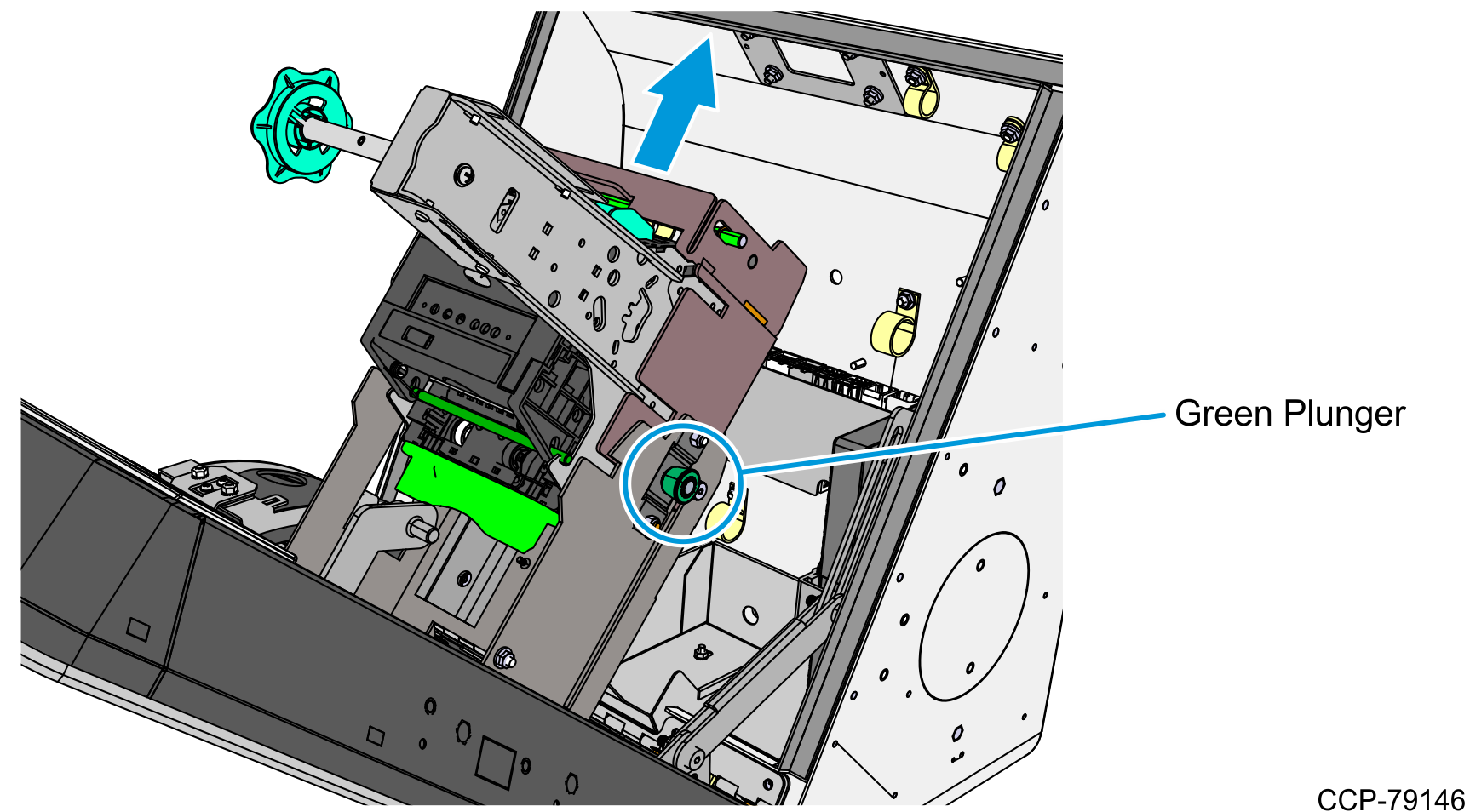
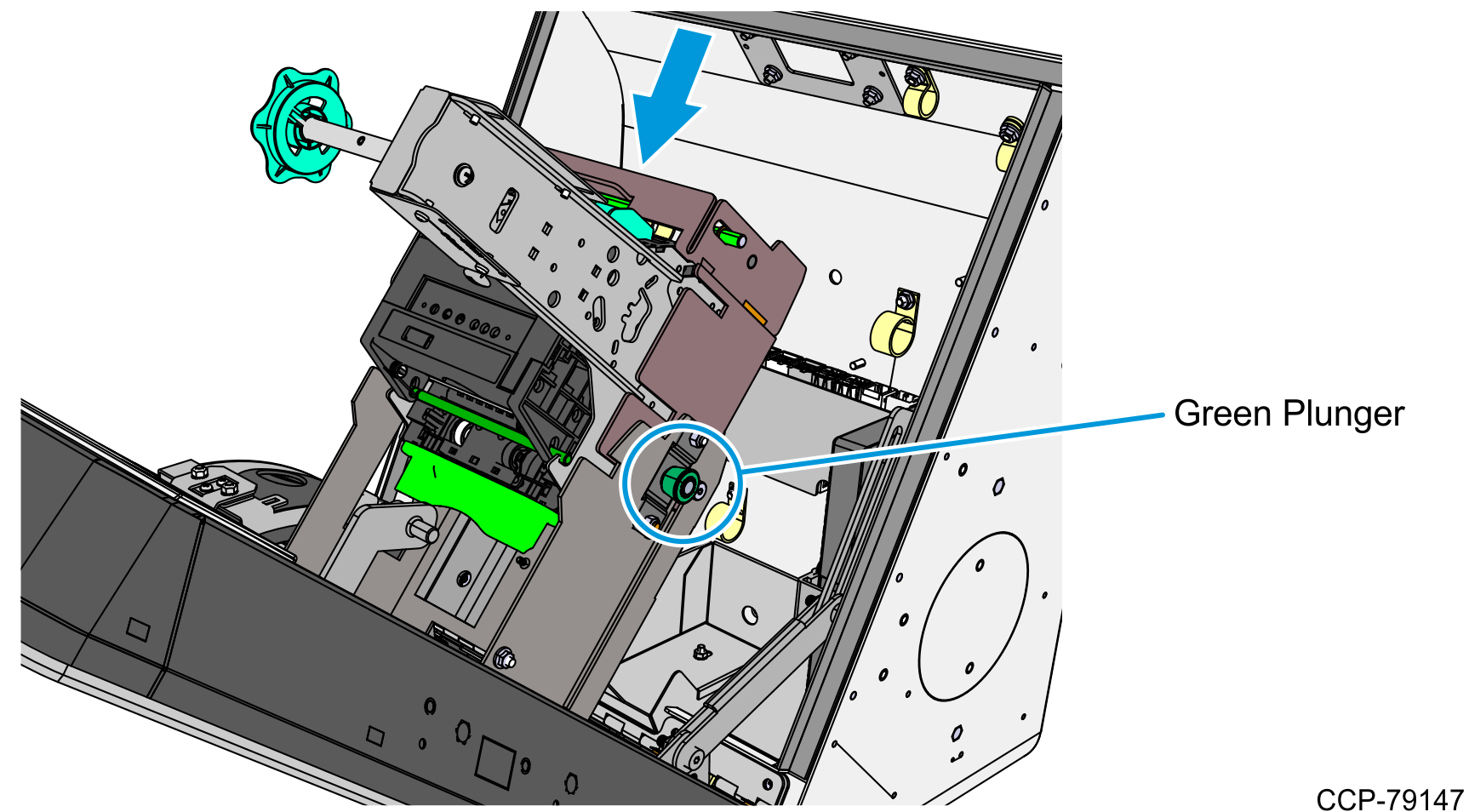
- Pull the printer assembly backward until fully extended and until the green plunger snaps into place.Caution
Ensure that the green plunger holds the printer assembly in place. Do not release the printer assembly if it is not yet secured by the green plunger.
- Push the green release rod upward.
- Connect the Printer USB Power Cable.
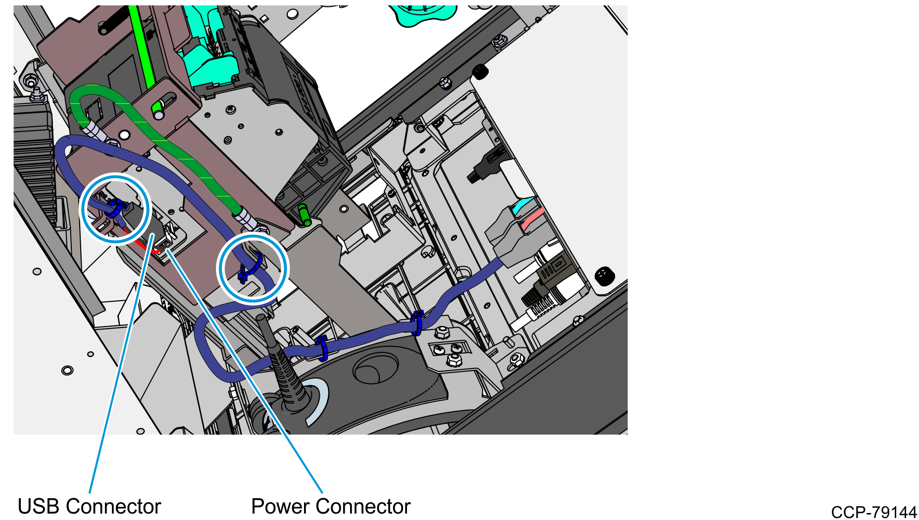
- Connect the Printer USB and Power Connector to the printer, route the cable towards the motherboard, and connect it to Port F of the motherboard.
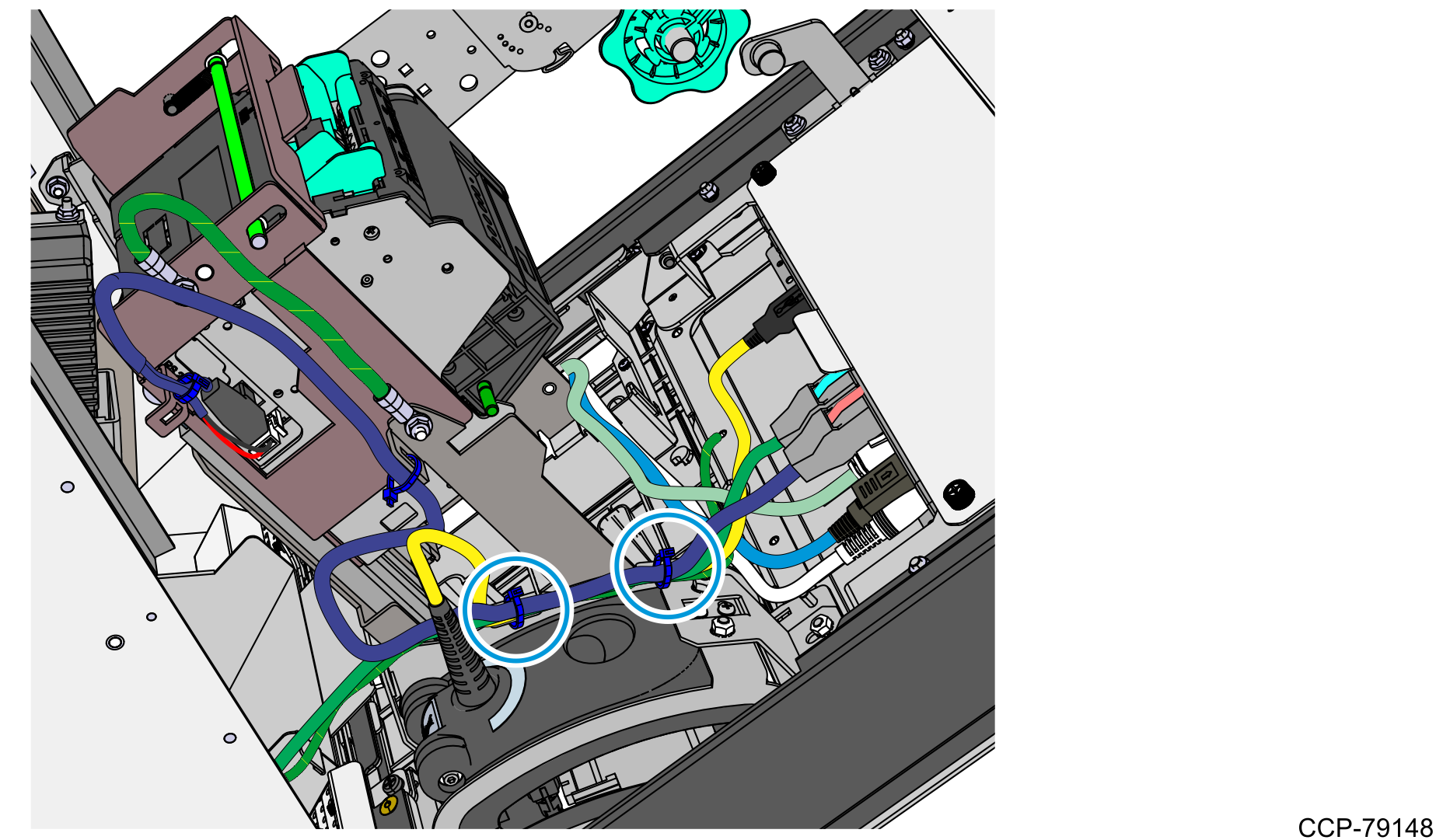
- Use two cable ties to secure the Printer USB and Power Cable to the Printer Bracket and to the Printer Tray.Note
There should be enough slack to allow the Printer Tray to slide upward.
- Bundle the Printer USB Power Cable together with other cables and use two cable ties to secure them to the Imager Bracket.
- Bundle the following cables together and use two cable ties to secure them to the Imager bracket:
- Imager USB cable
- Printer USB and Power cable
- I/O Daughter Card Power cable
- Motherboard Grounding cable
- Slide the printer assembly downward into operating position.
- While holding the green release rod, pull the green plunger and slowly slide the printer assembly downward until the green release rod latches onto the printer tray.Caution
Do not abruptly release the printer assembly when pulling out the green plunger. Hold and guide the printer assembly downward until it is fully seated on the printer tray.
- Using a new M4 nut, secure the other end of the Motherboard Grounding cable to the metal stud on the inner left wall of the cabinet.