5976 Customer Display
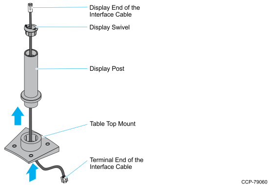
1.Route the display end of the Interface Cable through the Table Top Mount (5934-K021), the Display Post (5934-K021), and the Display Swivel (5977-K160).
Note: The terminal end of the Interface Cable is too large to fit down through the post.
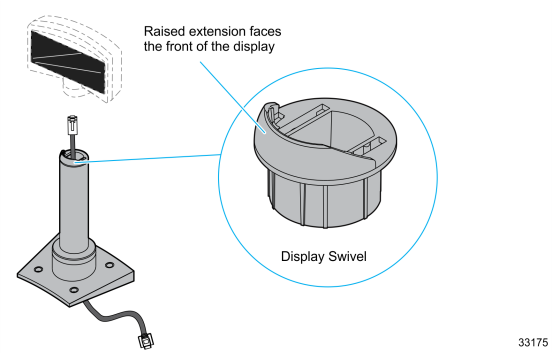
2.Assemble the post components.
Note: The raised extension of the Display Swivel is oriented toward the front of the unit, which permits the Display to be tilted to the rear.
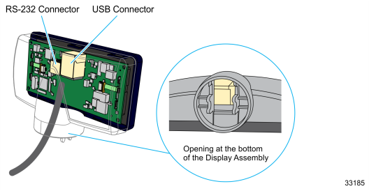
3. Insert the Interface Cable through the opening at the bottom of the Display Assembly and connect the Interface Cable to the designated connector on the Display Module.
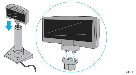
4.Connect the display to the post assembly
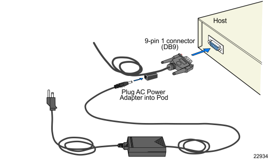
5.Connect the terminal end of the Display Cable to the host terminal.
•RS–232 Interface (Powered)
Connect the I/F cable to a powered RS–232 connector on the terminal.
•RS–232 Interface (Non–Powered)
Connect the I/F cable to a non–powered RS–232 connector on the terminal. Connect a Power Brick to the I/F cable and an AC outlet.
Configure the terminal serial port as follows:
9600 baud, 8 data bits, 1 start bit, 1 stop bit, No parity
•USB Interface (Powered)
Connect the I/F cable to a powered 12V USB + Power connector on the terminal.
•USB Interface (Non–Powered)
Connect the I/F cable to a non–powered USB connector on the terminal. Connect a Power Brick to the I/F cable and an AC outlet.