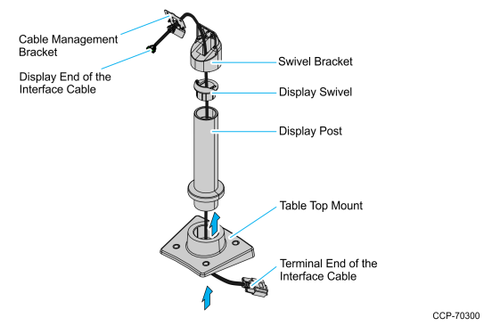
Using Cable Management Bracket
1.Route the display end of the Interface Cable through the Table Top Mount (5934-K021), the Display Post (5934-K021), the Display Swivel (5977-K160), the Swivel Bracket, and the Cable Management Bracket.
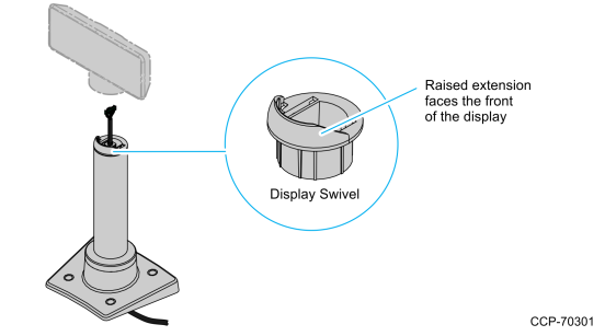
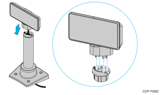
2.Assemble the post components.
Note: The raised extension of the Display Swivel is facing the front of the unit, which permits the Display to be tilted towards the back.
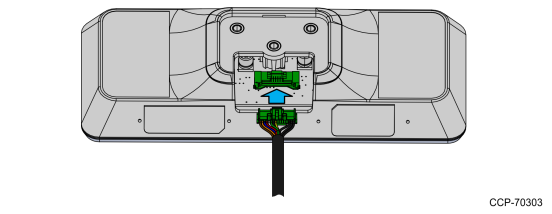
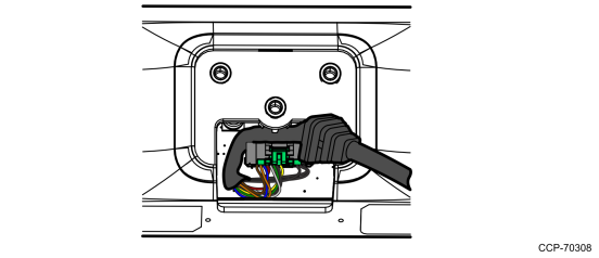
3.Connect the Interface Cable to the Display Module connector until the latch is engaged. Ensure that the latch is properly engaged by gently tugging on the cable.
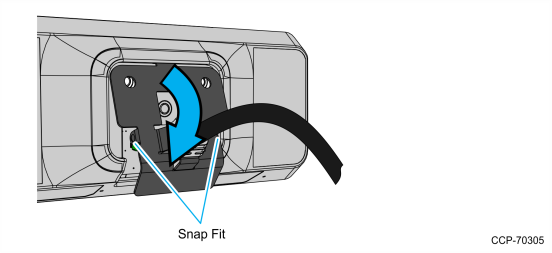
4.Slide the grooves of the Cable Overmold onto the tabs of the Cable Management Bracket.
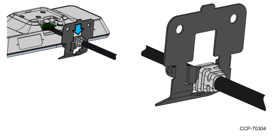
5.Route the excess cable to the right and around the board connector and install the Cable Management Bracket. Insert the tab of the Cable Management Bracket into the slot in the Rear Cover. Pivot the bracket as shown until it snaps into position.
Note: Ensure that the cables are not pinched when installing the bracket.
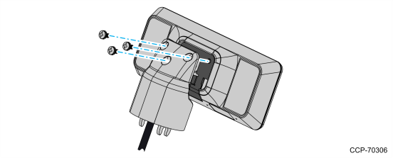
6.Install the Swivel Bracket by using the three M4x8 screws.
7.Connect the display to the post assembly.
8.Connect the terminal end of the Display Cable to the host terminal.
•RS–232 Interface (Powered)
Connect the I/F cable to a powered RS–232 connector on the terminal.
Configure the terminal serial port as follows:
9600 baud, 8 data bits, 1 start bit, 1 stop bit, No parity
•USB Interface (Powered)
Connect the I/F cable to a powered 12V USB + Power connector on the terminal.
•USB Interface (Non–Powered)
Connect the I/F cable to a non–powered USB connector on the terminal. Connect a Power Brick to the I/F cable and an AC outlet.