7879-K400 Color Sensor Assembly Upgrade
This kit contains the components to upgrade the NCR 7879 Imaging Bi–optic Scanner with a Color Sensor.
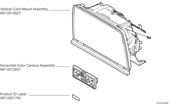
Kit Contents
Procedure
Warning: Be sure that power is removed from the NCR 7879 before performing this procedure.
Caution: Do not permit dust, dirt, debris, or any other contaminants to enter the NCR 7879 base.
These are the general steps to upgrade the NCR 7879 Imaging Bi–optic Scanner with a new Color Sensor:
1.Remove the Top Plate.
2.Remove the Tower Cabinet.
3.Remove the existing Vertical Mount Assembly.
4.Remove the existing Horizontal Camera Assembly.
5.Install the new Horizontal Color Camera Assembly.
6.Install the new Vertical Color Mount Assembly.
7.Reinstall the Tower Cabinet.
8.Affix the new Product ID Label.
9.Connect the cables to the Scanner.
10.Reinstall the Top Plate.
11.Verify the Scanner is operational.
For detailed instructions, refer to the succeeding sections.
Removal
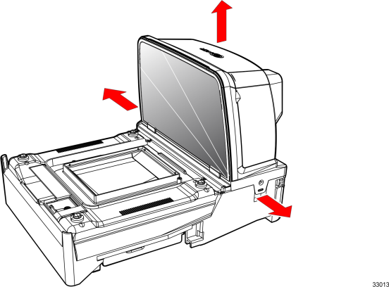
Top Plate
1.Hold the front edge of the Top Plate between your fingers.
2.Lift the Top Plate to remove it from the NCR 7879.

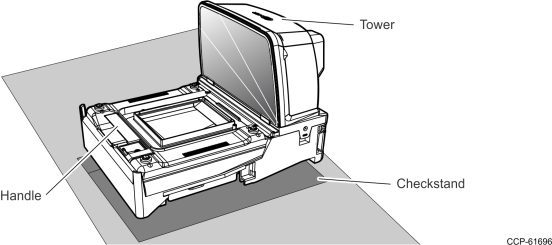
3.If the Scanner is in a Checkstand, lift out the Scanner by grasping the back of the Tower and the front handle.
4.Disconnect all cables from the back of the Scanner.
Tower Cabinet
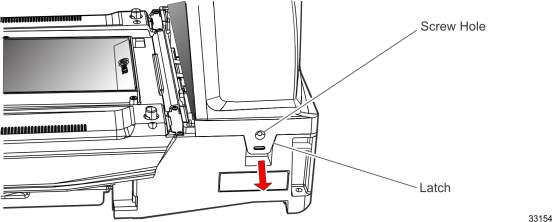
The Tower Cabinet is secured with two Latches, one on each side.
1.The Latches may be secured with a Screw; however, Screws are not installed during manufacturing. If Screws are being used, remove them so that the Latches are permitted to move out and release from the Horizontal Base Assembly.
2.Move the two Latches toward the outside of the scanner to release them.
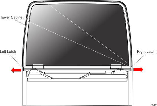
3.While holding the Latches out, lift the Tower Cabinet up and off the NCR 7879.
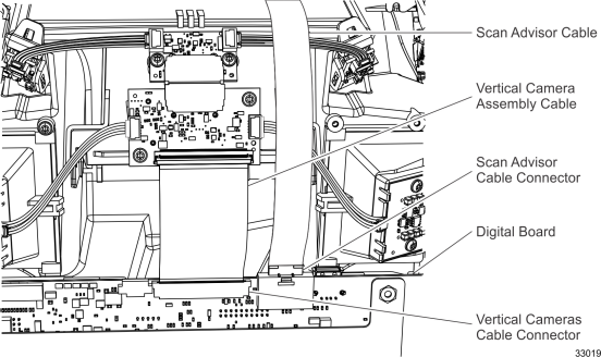
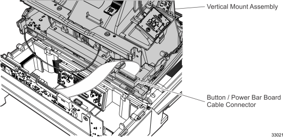
Vertical Mount Assembly
1.Disconnect the Vertical Camera Assembly Cable and the Scan Advisor Cable from the Digital Board. The Vertical Camera Assembly Cable connects to a compression connector that must be opened to remove the cable.
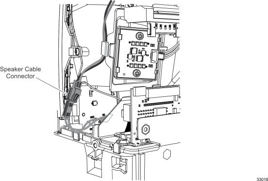
2.Disconnect the Speaker Cable.
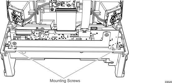
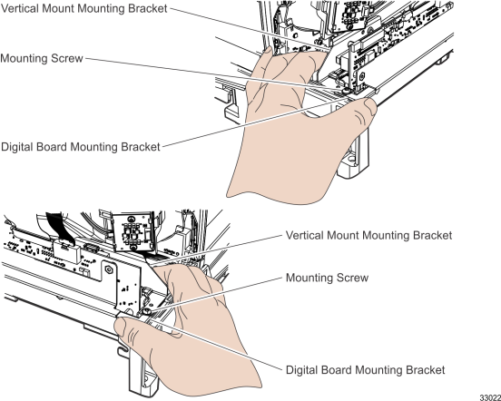
3.Remove the two Mounting Screws. These screws also secure the Digital Board Mounting Bracket.
4.Slide the Vertical Mount Assembly forward to unlatch the front of it.
5.Carefully rotate the top of the Vertical Mount Assembly toward the back of the NCR 7879, disengaging the Mounting Bracket from the Mounting Screws. Lift the Vertical Mount Assembly up from the unit; however, it cannot be removed from the NCR 7879 yet, there are still two cables connected.
6.Lay the front of the Vertical Mount Assembly on the Horizontal Scan Window.
7.Disconnect the Button / Power Bar Board Cable.
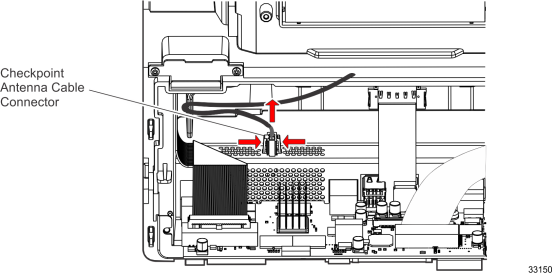
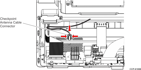
8.Disconnect the Checkpoint cable. Use Needle Nose Pliers to squeeze the connector latches toward the connector and then move the connector toward the front of the NCR 7879 to disconnect it.
9.Lift the Vertical Mount Assembly off the NCR 7879.
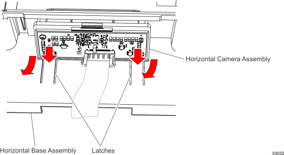
Horizontal Camera Assembly
Note: The Vertical Mount Assembly must be removed before the Horizontal Camera Assembly.
1.Press the two Latches in the Horizontal Base Assembly and rotate the bottom of the Horizontal Camera Assembly toward the back of the NCR 7879; lift the Horizontal Camera Assembly out of the unit.
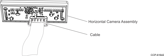
2.Disconnect the Cable from the Horizontal Camera Assembly.
Installation
Horizontal Color Camera Assembly
1.Connect the Cable to the Horizontal Color Camera Assembly.
2.Position the Tab on the top of the Horizontal Color Camera Assembly under the Metal Latch on the Horizontal Base Assembly.
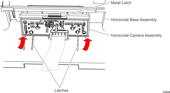
3.Push the bottom of the Horizontal Color Camera Assembly into place. The Latches should snap into place, securing it.
Vertical Color Mount Assembly
1.Carefully lay the front of the Vertical Color Mount Assembly on the NCR 7879 Vertical Scan Window. The bottom of the Vertical Color Mount Assembly goes toward the back of the NCR 7879.
2.Connect the Checkpoint cable. Using Needle Nose Pliers, slide the connector on the end of the Checkpoint cable into the connector. Make sure the latches engage.
3.Connect the Button / Power Bar Board Cable to the connector on the board.
4.Pick up the Vertical Color Mount Assembly and carefully guide the slots in the Mounting Bracket under the Mounting Screws.
5.Continually rotate the Vertical Mount Assembly into position with it as far toward the front of the unit as possible.
6.Slide the Vertical Color Mount Assembly toward the back of the NCR 7879, latching the front of the Vertical Color Mount Assembly.
7.Loosely install the two Mounting Screws through the holes in the Vertical Color Mount Assembly and the Digital Board Mounting Bracket.
8.Hold one side of the Vertical Color Mount Assembly in place by using your thumb and index finger to squeeze the Vertical Color Mount Mounting Bracket and the Digital Board Mounting Bracket. While holding this position, tighten the Mounting Screw. Repeat this step for the other side of the Vertical Color Mount Assembly.
9.Connect the Speaker Cable.
10.Connect the Vertical Cameras Cable and the Scan Advisor Cable to the Digital Board. Make sure the Vertical Cameras Cable is properly positioned between the guides in the connector and then close the compression bar on the connector.
Tower Cabinet
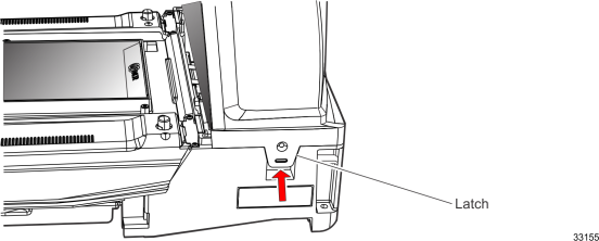
1.Carefully position the Tower Cabinet down over the Tower Assembly. Make sure it is properly positioned on the NCR 7879 so that the Side Latches can engage.
2.Slide the Tower Cabinet down to engage the latches.
3.Slightly push the Latches toward the center of the scanner to make sure they are engaged.
4.If Screws were used in the Latches, install and tighten the Screws.
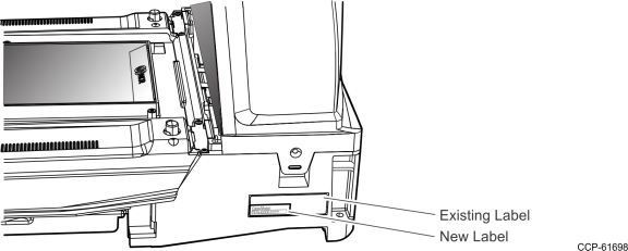
Product ID Label
Affix the new Product ID Label over the lower left corner of the existing label to update the Scanner's Class/Model Number.
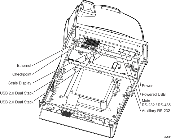
Cables
1.Connect the external cables to the Scanner.
2.If applicable, reinstall the Scanner to the Checkstand. Grasp the back of the Tower and the front handle, then lower down the Scanner into the Checkstand.
Top Plate
1.Position the Top Plate over the front of the NCR 7879.
2.Lower the Top Plate until it is supported by the Supporting Studs. The Top Plate should be properly aligned with the NCR 7879 and should not move in a horizontal direction.
Note: If the NCR 7879 includes a scale, the Supporting Studs are part of the Scale Assembly.
Verify NCR 7879 is Operational
Turn on the NCR 7879 and run some sample tags to verify the unit is operational. If an error occurs, refer to Chapter 3: Troubleshooting of the NCR RealScan™ 79 (7879) Hardware Service Guide (B005-0000-2300).