7878-K153 Imaging Assembly (Compact Scanner)
This Imaging Assembly (7878‐K153) provides imaging capabilities for the NCR RealScan 78 Compact Bi–Optic Scanners. This document explains how to install the kit on the 7878 scanner.
Kit Contents
Tools Needed
•Phillips Screw Driver #2
• USB Flash Drive
Software Tools Needed
•Firmware — 497‐0472618 or later versions
• NCR Scanner Flash Drive Prep Tool or NCR Scanner Flash Tool
Note: These tools are available for download at the NCR scanner website http://www5.ncr.com/support/support_drivers_patches.asp?Class=retail_RealScan
Installation Procedures
Warning: Disconnect the AC power cord before disassembling the Scanner.
These are the general steps to install the Imaging Assembly to the NCR RealScan™ 78
Bi–Optic Scanner (7878) :
1.Remove the Top Plate.
2.Remove the Front Bezel.
3.Remove the Tower Cover.
4.Install the Imaging Assembly.
5.Re–install the Tower Cover.
6.Install the New Hybrid Front Bezel.
7.Reinstall the Top Plate.
For detailed instructions, refer to the succeeding sections.
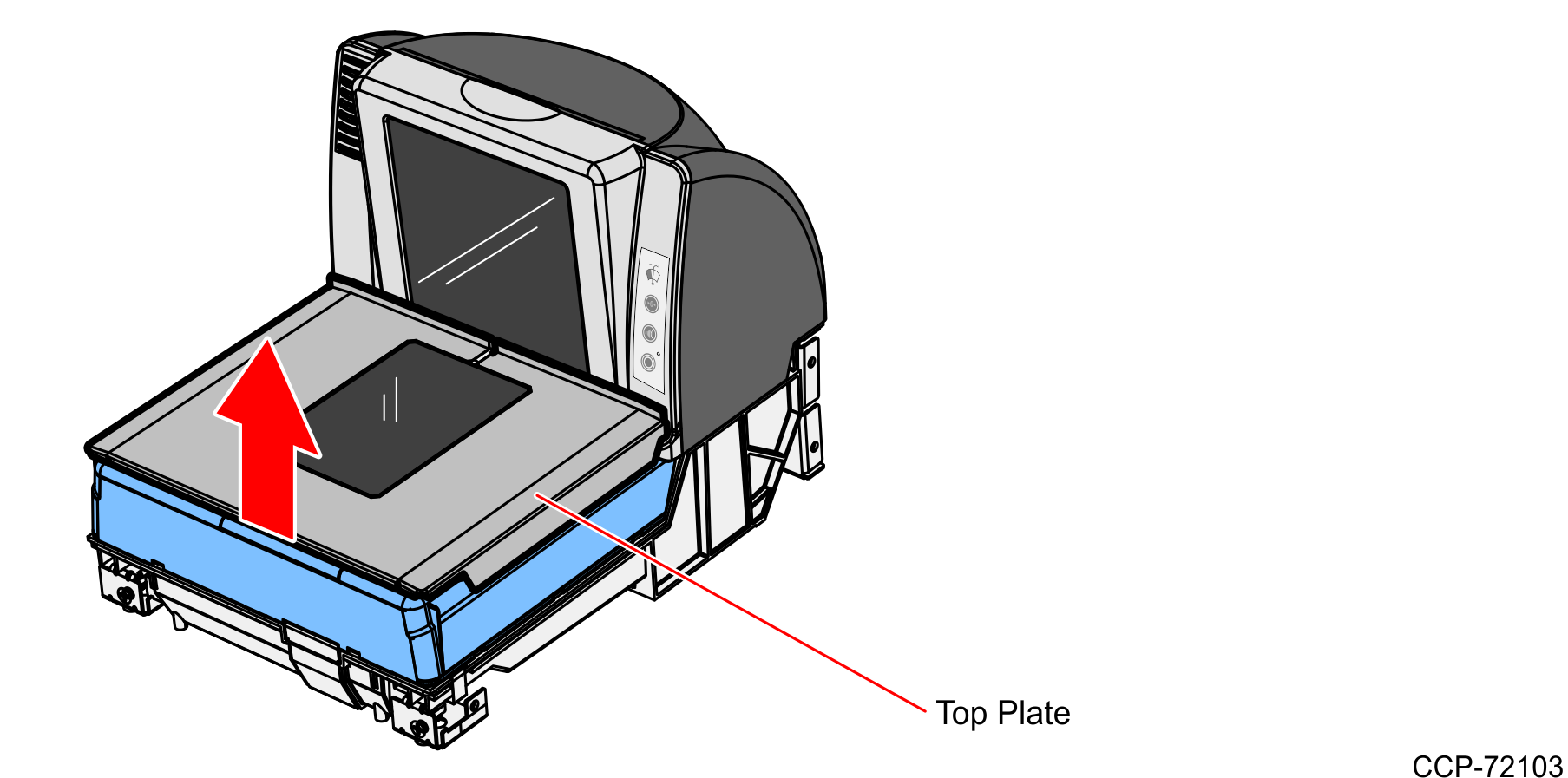
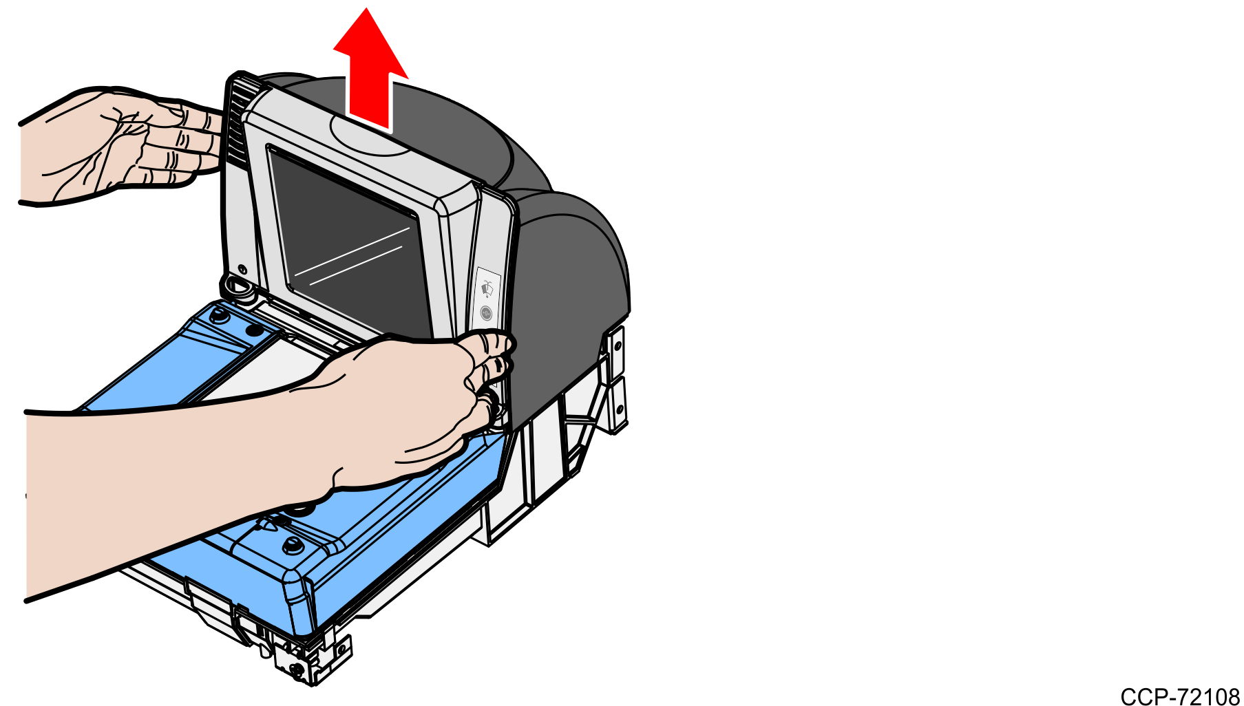
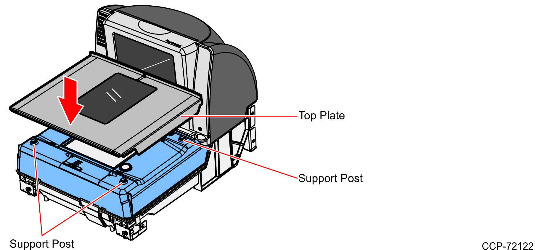
Remove the Top Plate
To remove the Top Plate, do the following:
1.Hold the front edge of the Top Plate until your fingers are underneath it.
2.Lift the Top Plate to remove it from the Scanner.
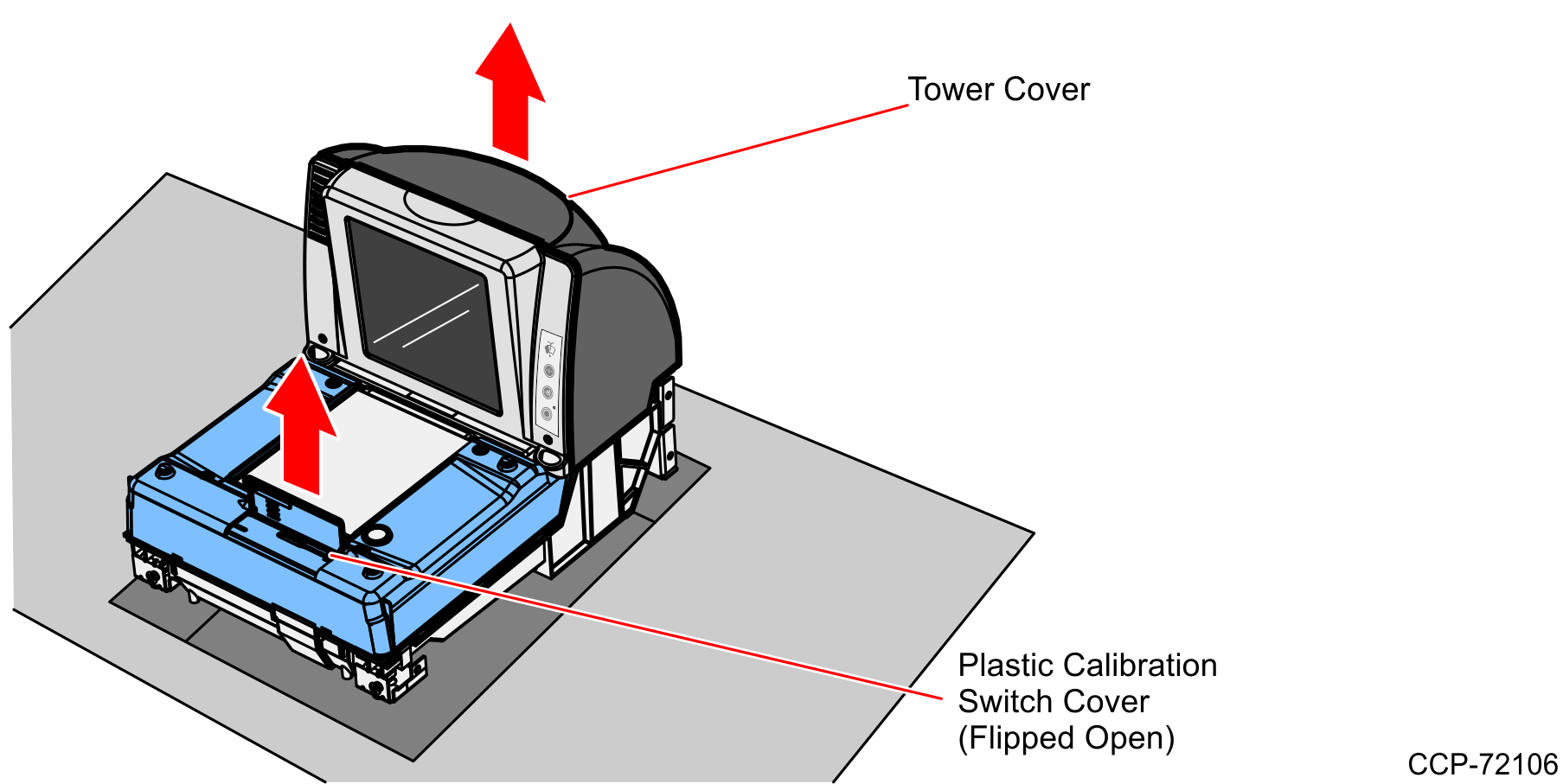
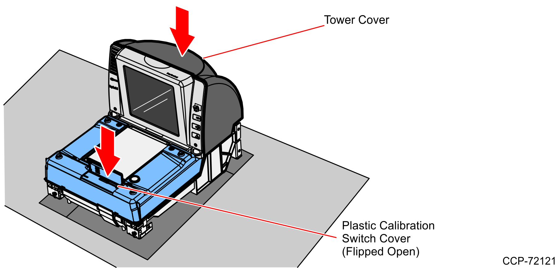
3.If the Scanner is in a Checkstand, lift out the Scanner by grasping the back of the Tower Cover with one hand and the plastic Calibration Switch Cover with the other hand.
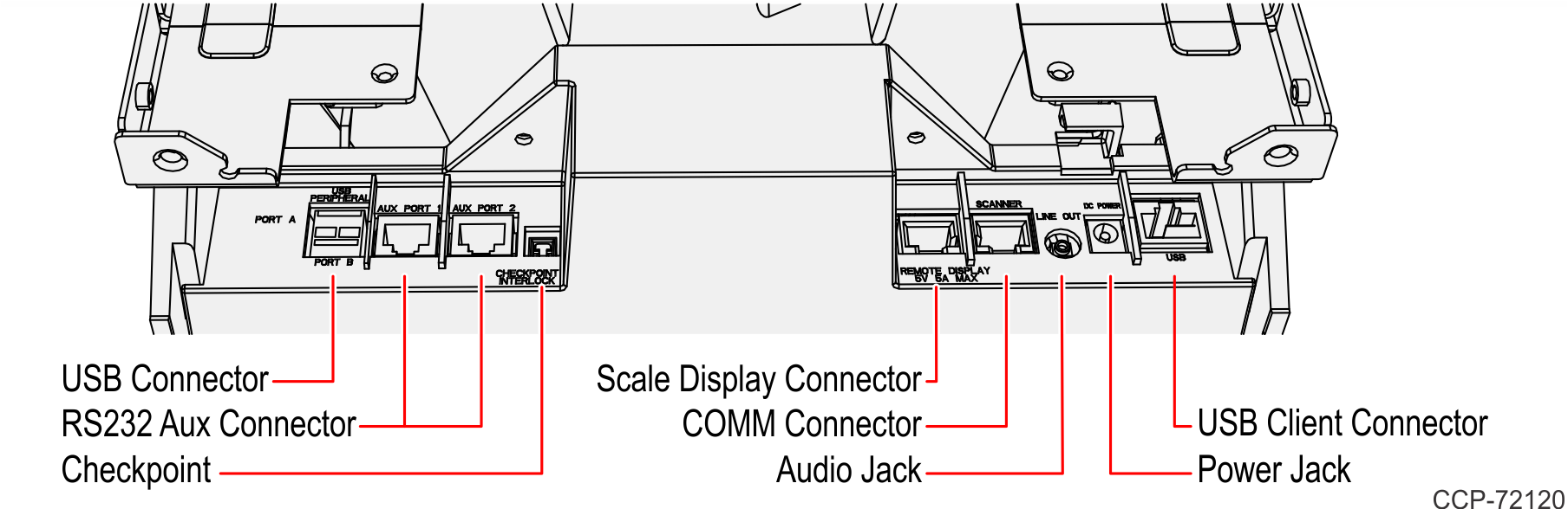
4.Disconnect all cables from the back of the Scanner.
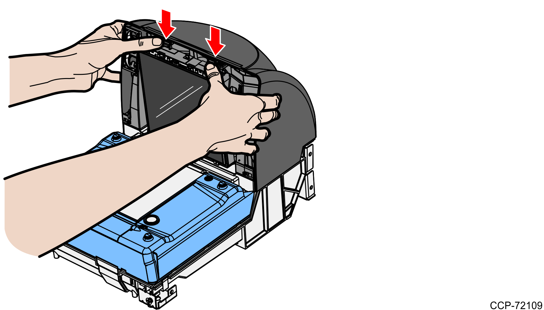
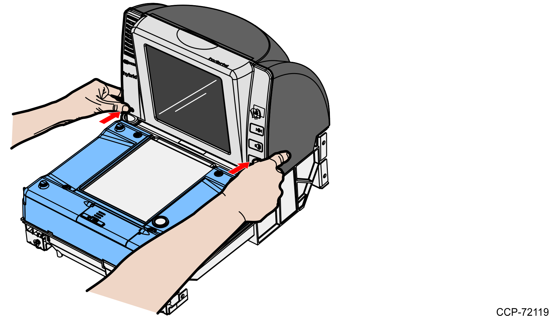
Remove the Front Bezel
To remove the Front Bezel, do the following:
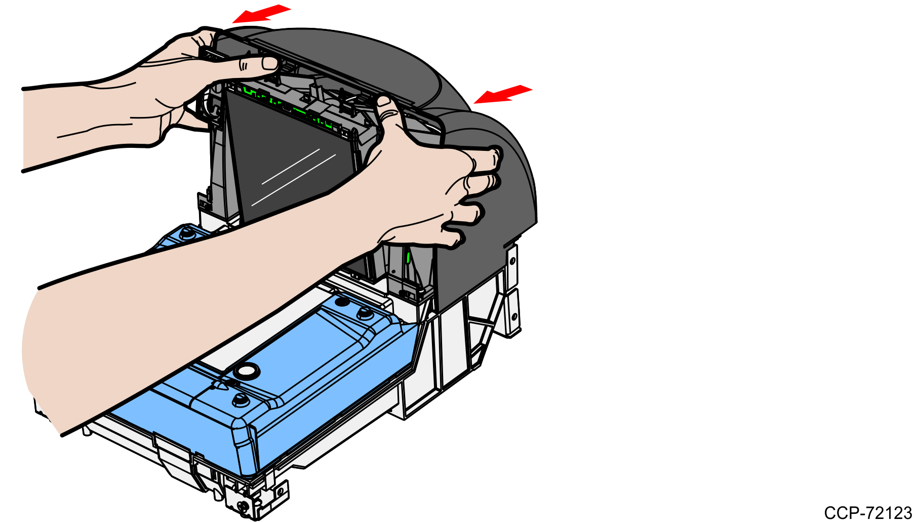
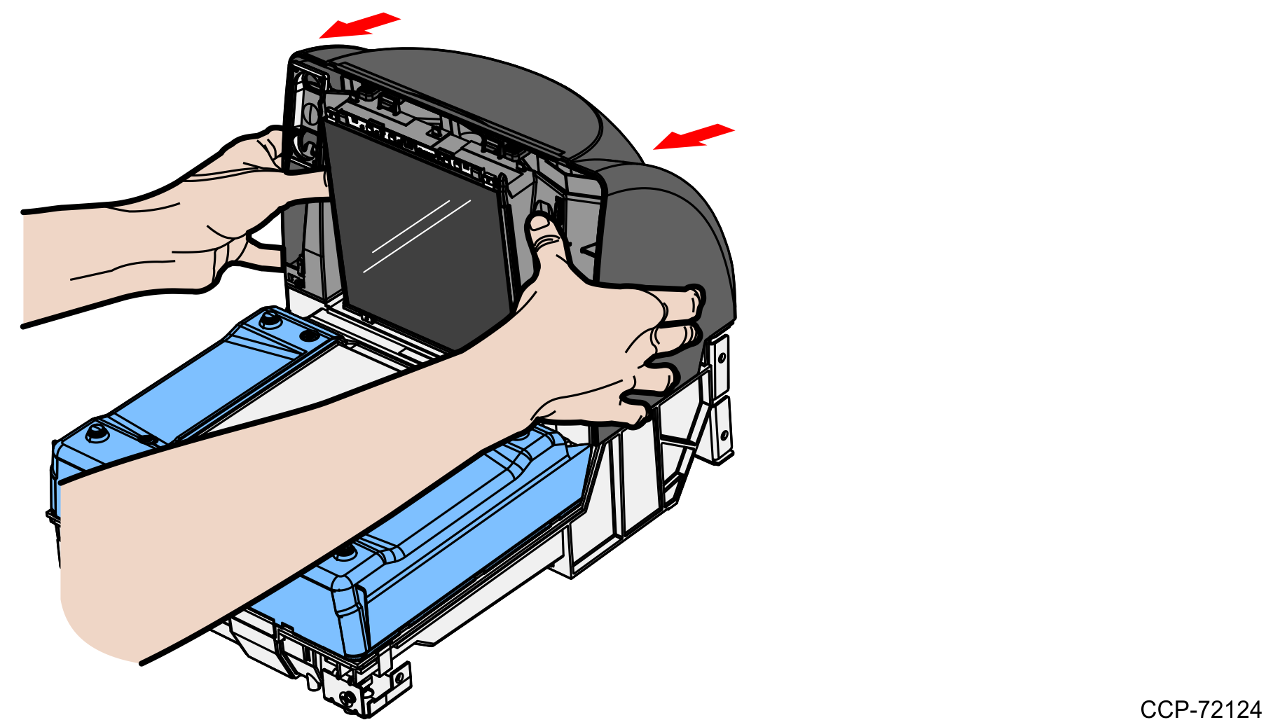
1.Place one hand and slightly apply pressure on the top corner of the Front Bezel and use the other hand to pull the snap features at the bottom.
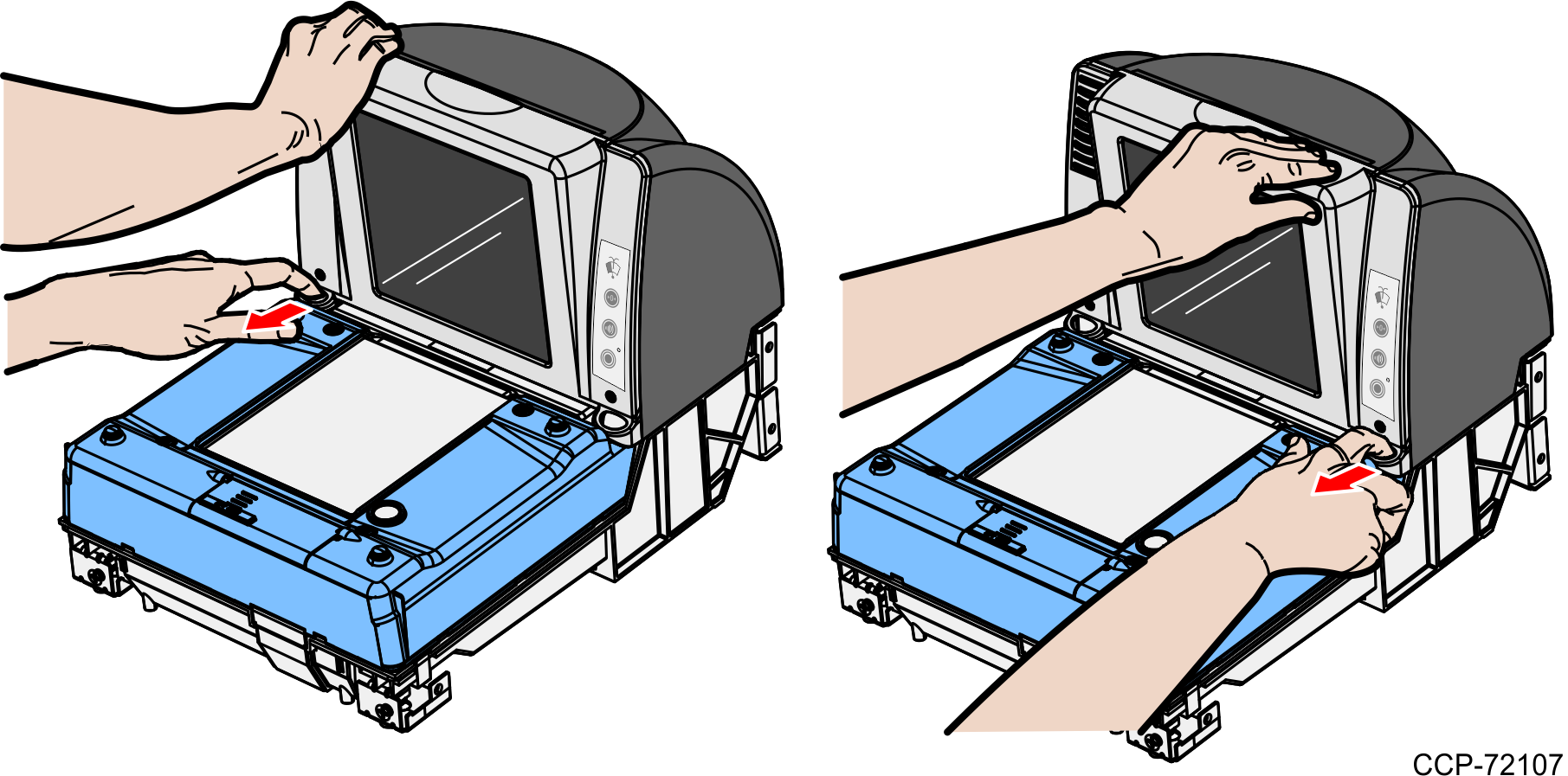
2.Lift the Front Bezel straight up to remove it from the Inner Tower.
Remove the Tower Cover
The Tower Cover covers the Vertical Optics Assembly. It is fastened to the 7878 Mounting Bracket without screws.
1.Depress the two tabs at the top of the Tower Cover to disengage the snap features.
2.Slide the Tower Cover towards the rear then lift it up until detached.

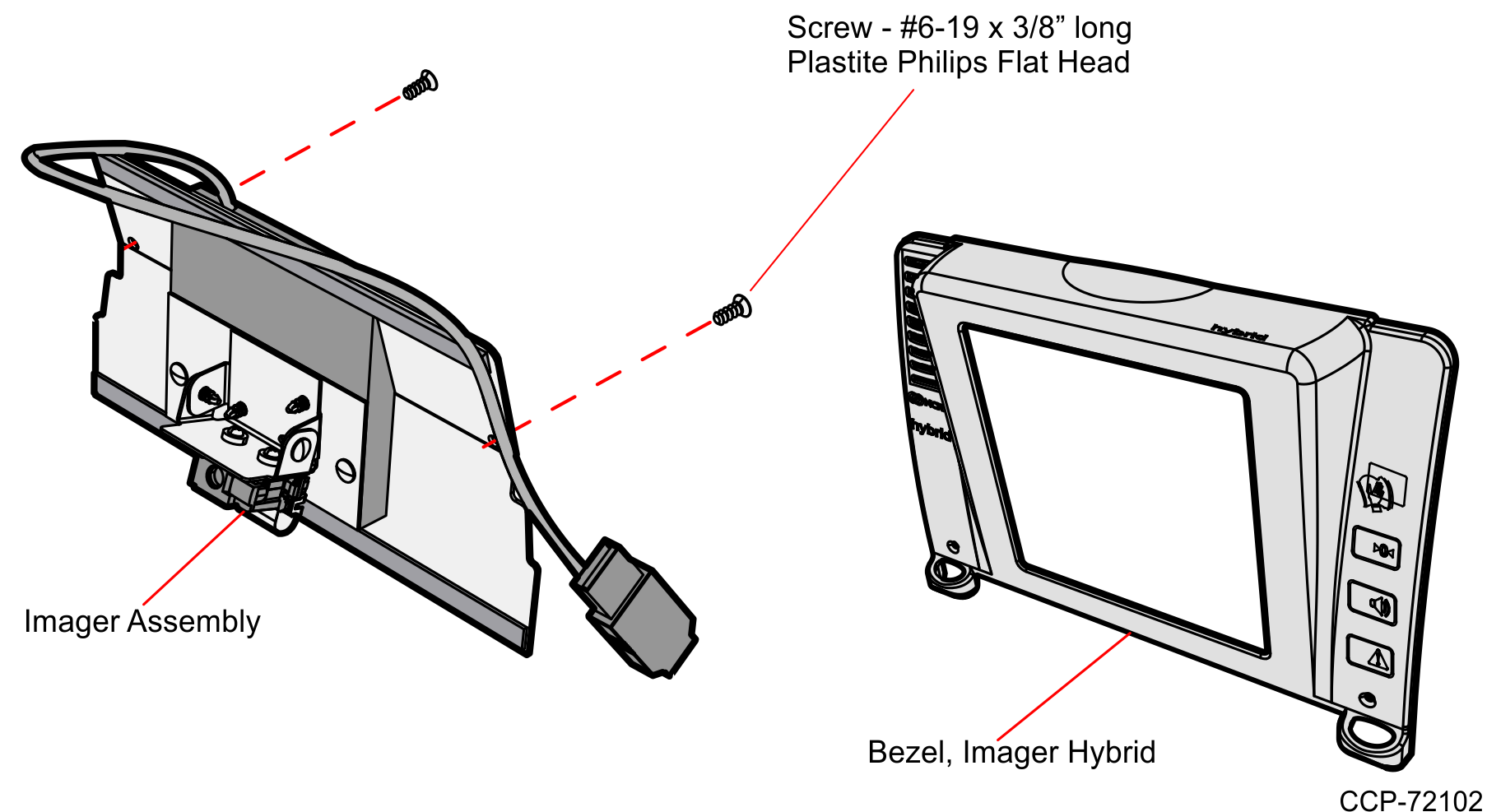
Install the Imaging Assembly
To install the Imaging Assembly, do the following:
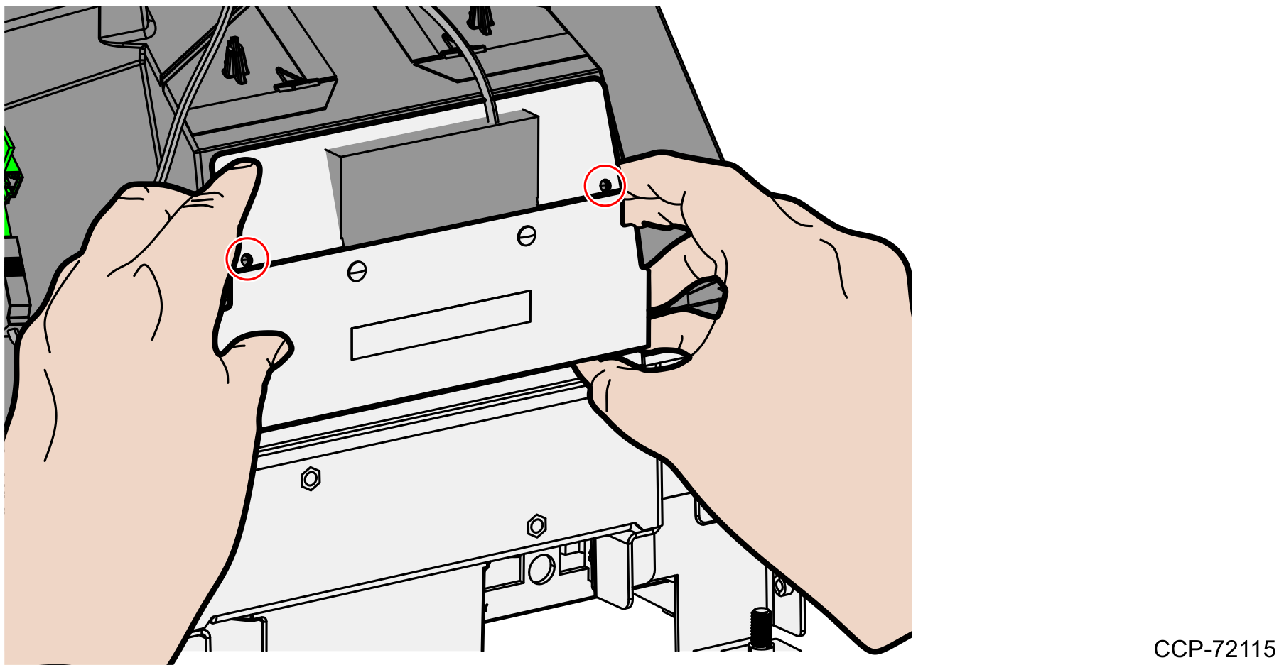
1.Remove the Blank Plate that is found at the back of the Optics Assembly.
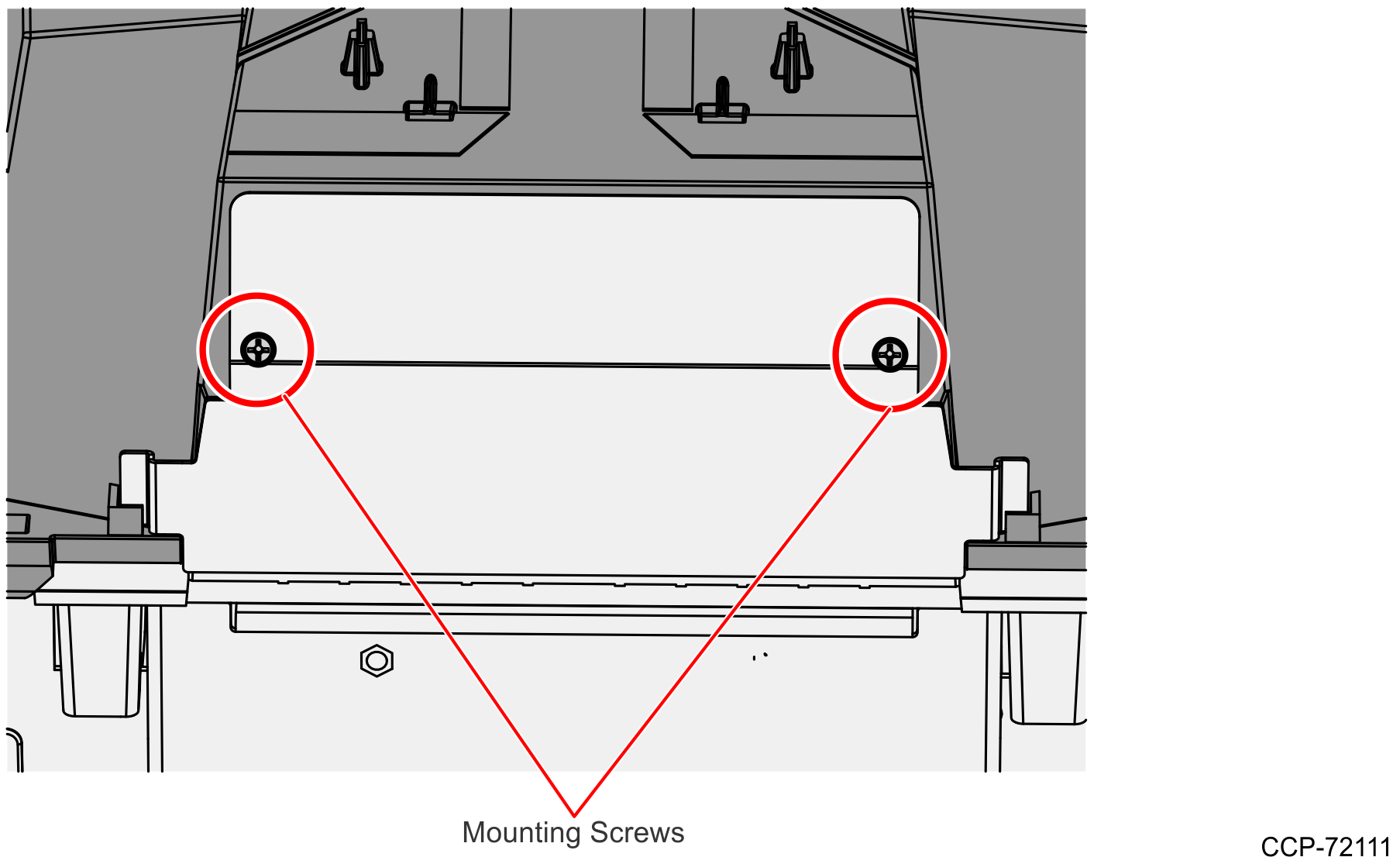
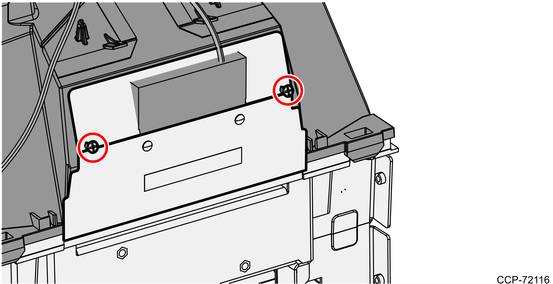
a.Remove the two Phillip screws indicated in the above image.
Note: Set aside the screws as they are needed upon installation of the Imager kit.
b.Slide the Blank Plate upward and then remove it from the Optics Assembly. Discard the Blank Plate.
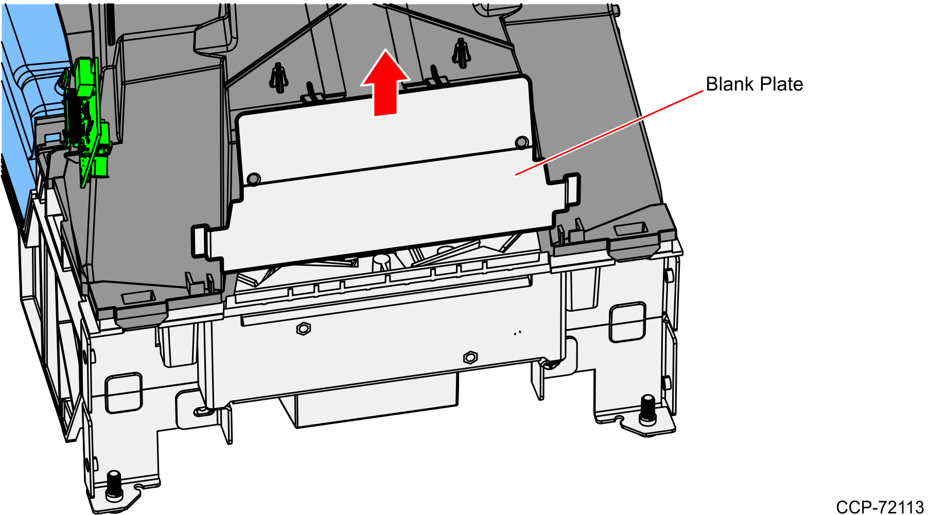
c.After discarding the Blank Plate, prepare the Imager Assembly for installation.
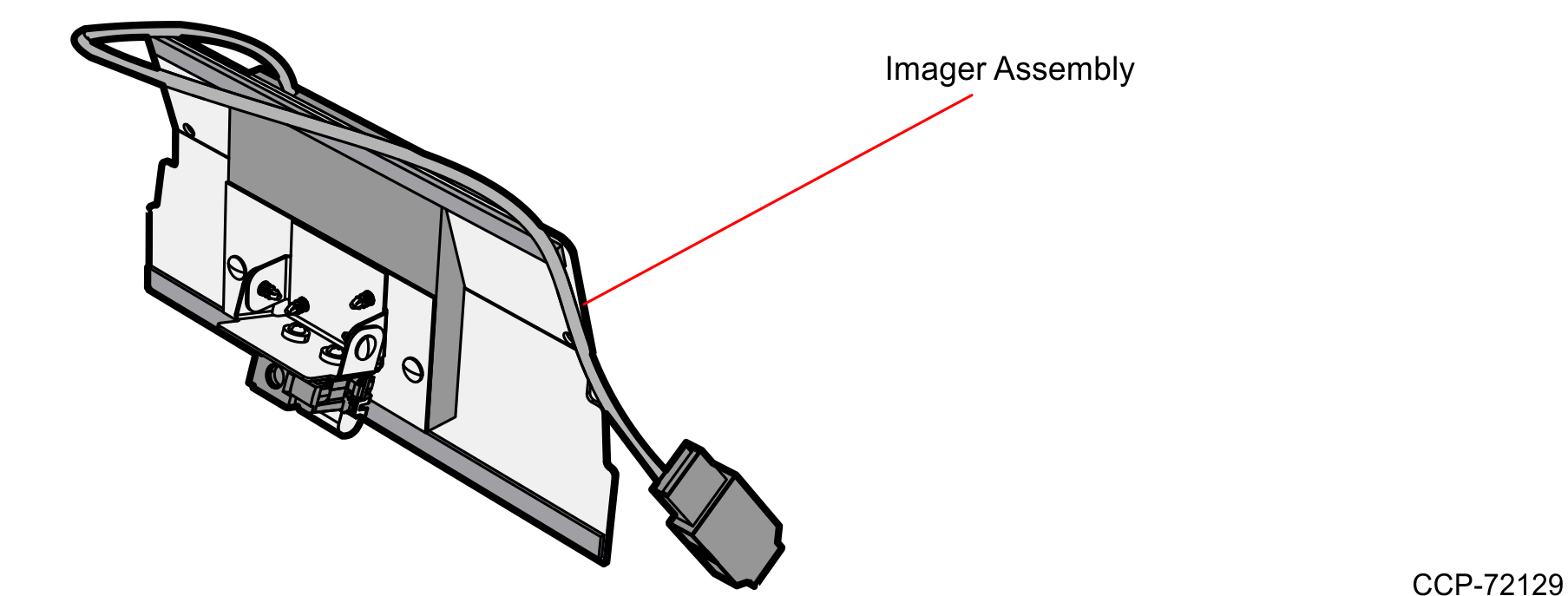
2.Remove the liner from one side of the adhesive tapes. Adhesive tapes are found on top and bottom edges of the Imager Assembly.
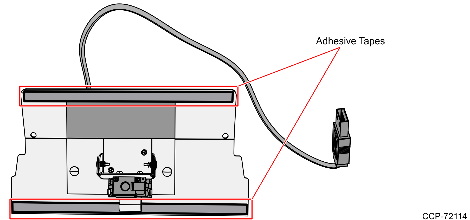
3.Align the holes of the Imager Mount with the mounting holes of the Optics Assembly.
4.Press the top and bottom edges of the Imager Mount to make them stick to the Optics Assembly.
Note: Ensure that the tapes on the Imager Assembly adequately adhere to the Optics Assembly. Spaces or openings between the Imager Assembly and the Optics Assembly should be avoided to prevent dust or debris from entering the optics chamber.
5.Holding the Imager Mount in place, insert the flat head screws to the mounting holes.
6.Tighten both screws to 6.25 lbs–in.
Note: Do not overtighten the screws to avoid breaking the mount.
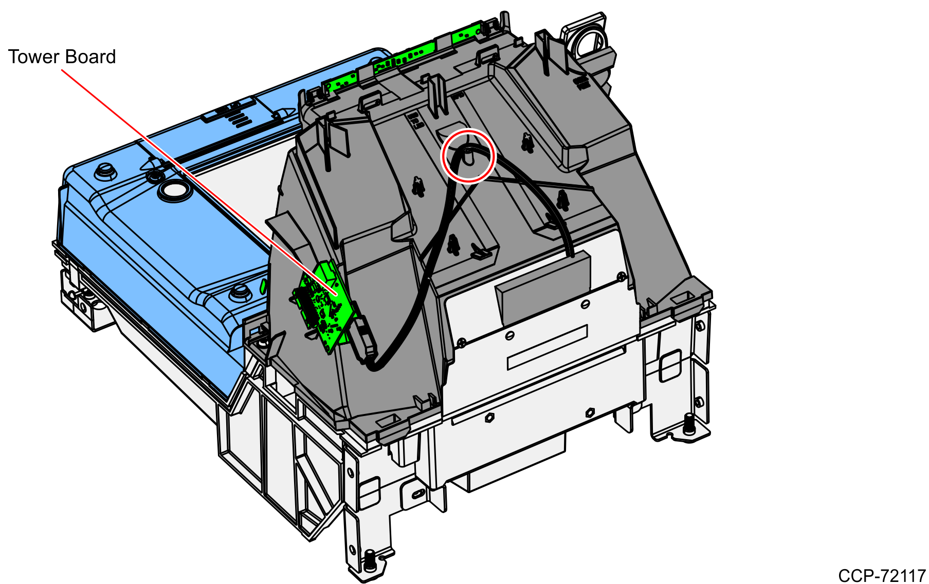
7.Route the Imager USB cable through the cable guide on the Optics Module, and then connect the Imager USB cable to the lower rear–facing tower USB peripheral port on the Tower Board.
Re-install Tower Cover
To re–install the Tower Cover, do the following:
1.Place the Tower Cover down onto the Inner Tower.
2.Ensure no wires or cables are pinched between the Tower Cover and the unit.
3.Slide the Tower Cover until the two tabs snap in.
Install the New Hybrid Bezel
To install the New Hybrid Bezel, do the following:
1.Align the top edge of the Tower Cabinet with the top edge of the New Hybrid Bezel.
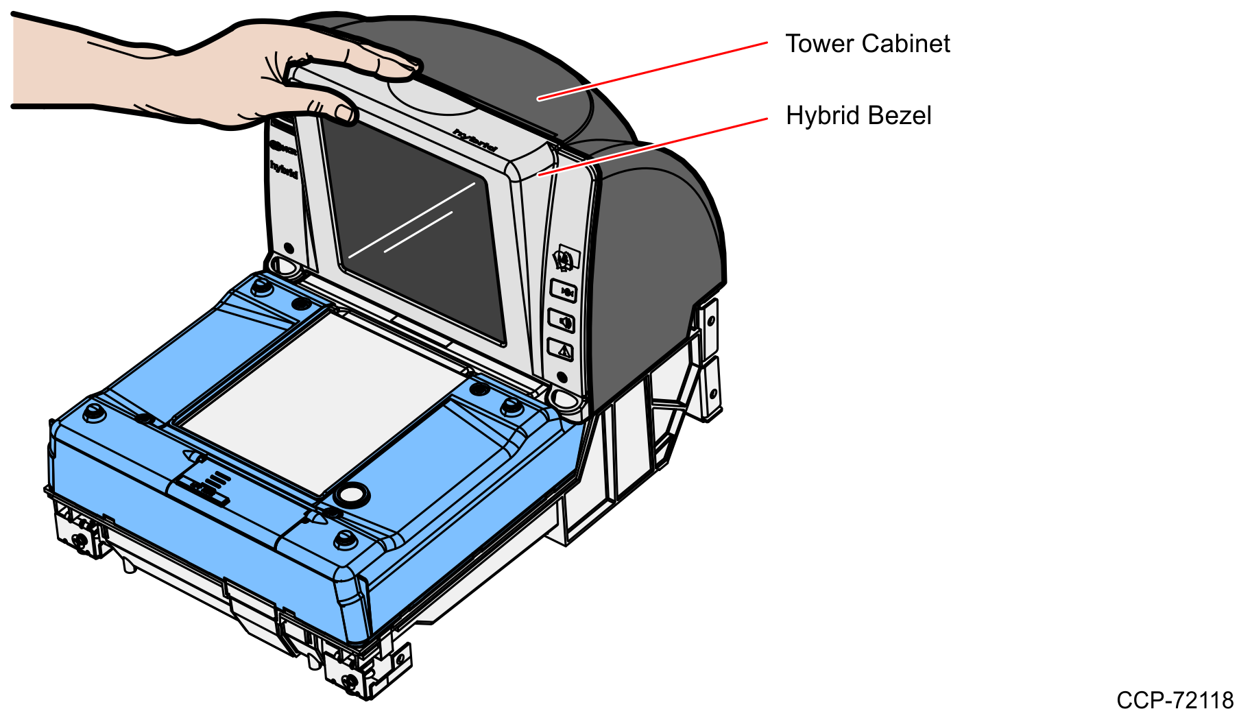
2.Apply pressure on the bottom‐left and bottom‐right corners of the New Hybrid Bezel to latch it in place.
3.Connect the external cables to the Scanner.
4.If applicable, reinstall the Scanner to the Checkstand. Grasp the back of the Tower Cover with one hand and the plastic Calibration Switch Cover with the other hand, then lower down the Scanner into the Checkstand.
Re–install the Top Plate
1.Lower the back edge of the Top Plate onto the two back Support Posts on the Scanner.
2.Holding the front edge, lower the front of the Top Plate onto the two front Support Posts.
3.Power on and program the scanner. For procedures on how to program the scanner, refer to Programming Instructions.