Routing the Checkpoint® Controller cables
To route the Checkpoint® Controller cables, follow these steps:
- Do the following:
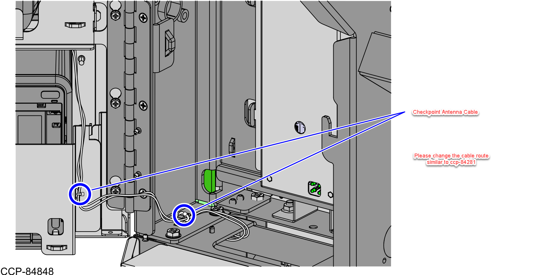
- Route the R6 Checkpoint® cable and Antenna Extender Cable on the left side of the Pedestal Cabinet.
- Continue routing the cables up to the Tower Cabinet.
- Using a cable tie, bundle the excess cable at the left side of the Pedestal Cabinet.Note
Do not bundle the Checkpoint® cables with the cables on the right side.
- Do the following:
-
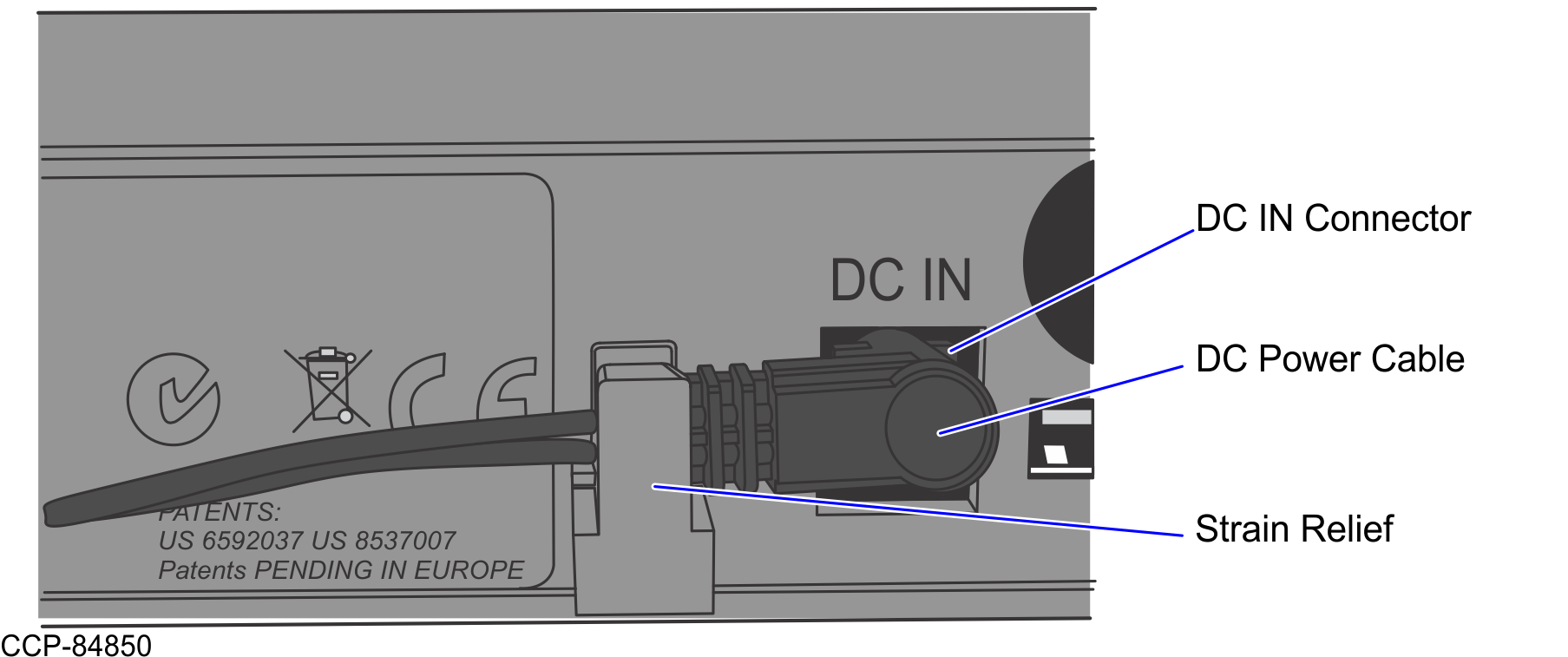
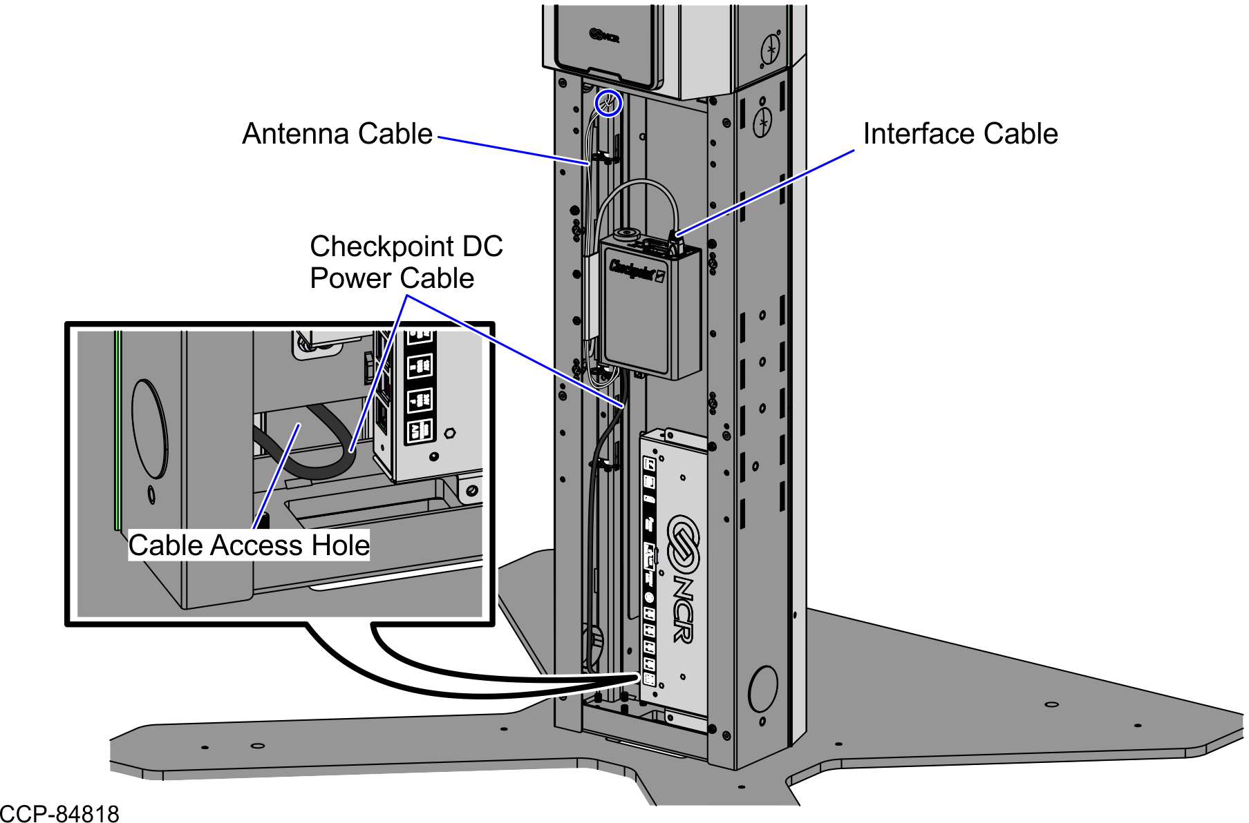
Connect the Checkpoint® DC Power cable to the DC In Port on the back of the Checkpoint® Controller and then secure the cable by sliding the jack behind the Strain Relief, as shown in the image below.
- Route the power cable down and through the rear cable access hole.
-
Connect the Checkpoint® DC Power cable to the DC In Port on the back of the Checkpoint® Controller and then secure the cable by sliding the jack behind the Strain Relief, as shown in the image below.
- Remove the Single Window Scanner. For more information, refer to Removing the Single Window Scanner (Datalogic Magellan 1500i).
- Do the following:
- Secure the Antenna Extender Cable on the bridge lance and with the Receipt Printer cable, as shown in the image below.
- Route the Antenna Extender Cable up to the Single Window Scanner.
- Loop the Antenna cable around the Scanner Window using the four (4) hook tabs as guide.
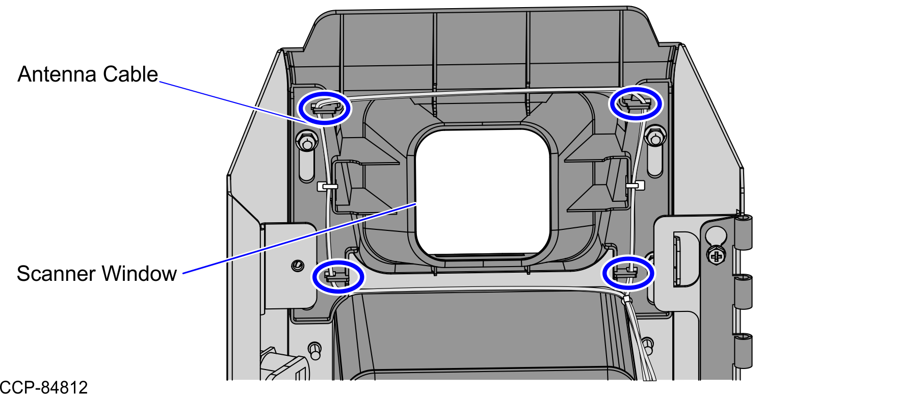
- Secure the Antenna cable using two (2) cable ties, as shown in the image below.
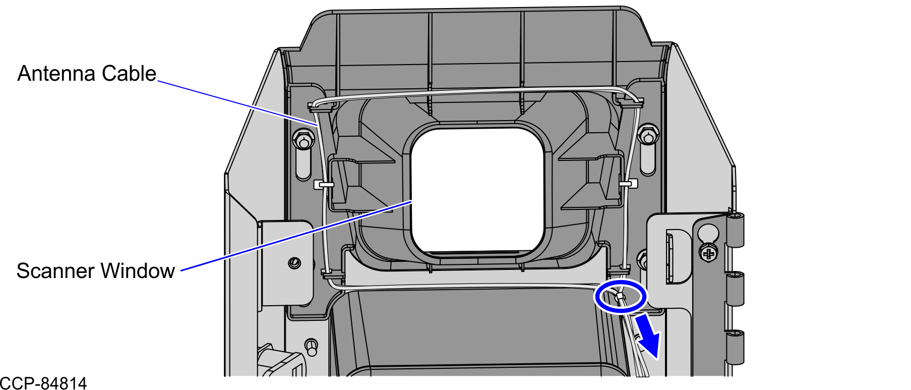
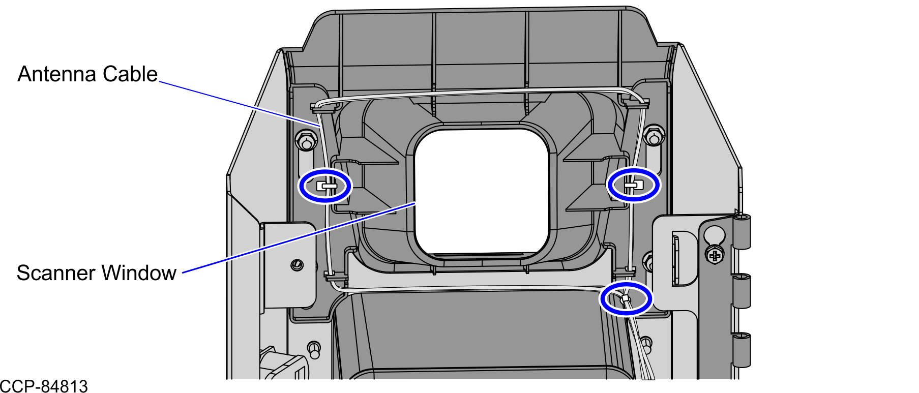 Note
NoteIf the cable loop is too tight, pull the cable tie on the lower right side downward, and then adjust the loop.
- Secure the Antenna Extender Cable on the bridge lance and with the Receipt Printer cable, as shown in the image below.
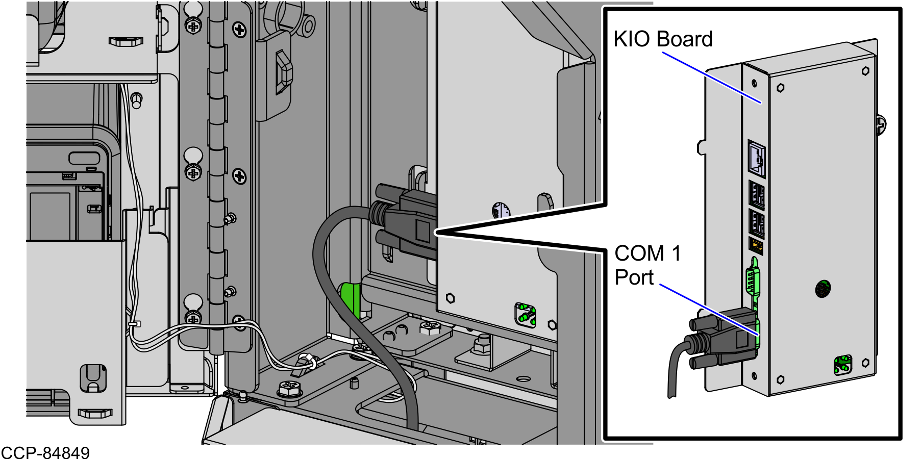
- Connect the Checkpoint® cable to the COM Port 1 of the KIO Board, as shown in the image below.