Installing the Checkpoint® Controller: No-Bag Configuration
To install the Checkpoint® Controller, follow these steps:
- Do the following:
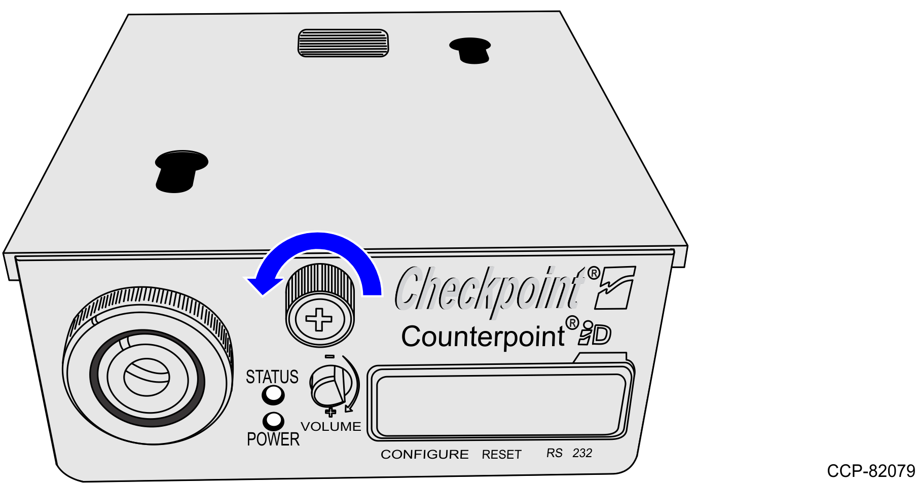
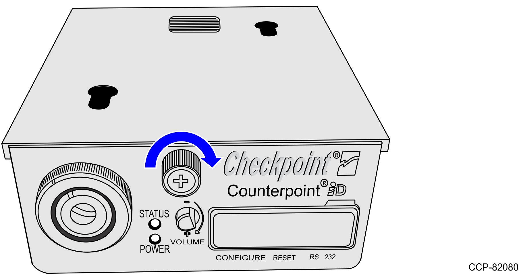
- On the front of the Checkpoint® Controller, turn the thumbscrew to the left and slide the top cover off the device.
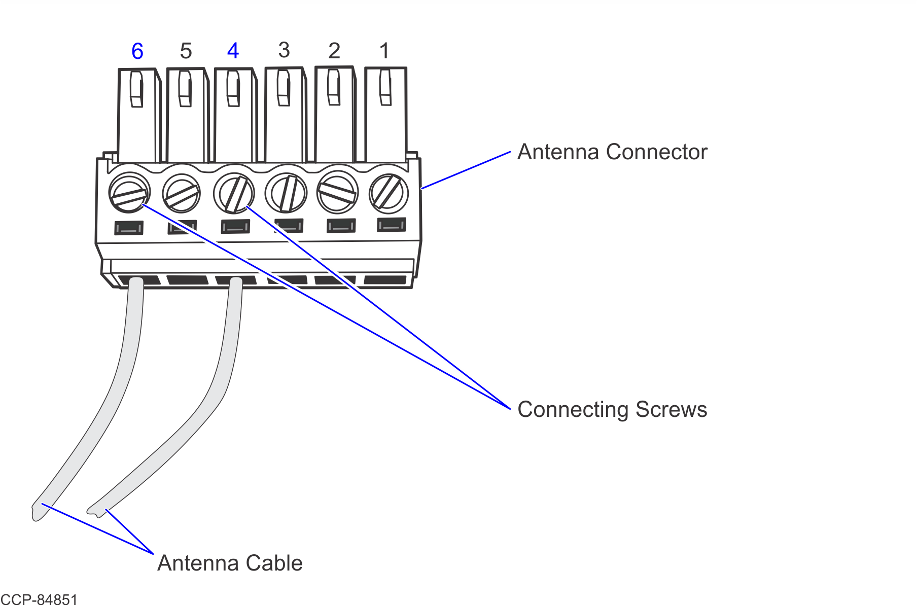
- Connect the Antenna cables to Pins 4 and 6 of the Antenna connector in the Controller. The Antenna Cable is an extension of the Checkpoint Antenna and consists of two white wires that are twisted together.Note
Use a small Flathead Screwdriver to loosen and tighten the two Connecting Screws.
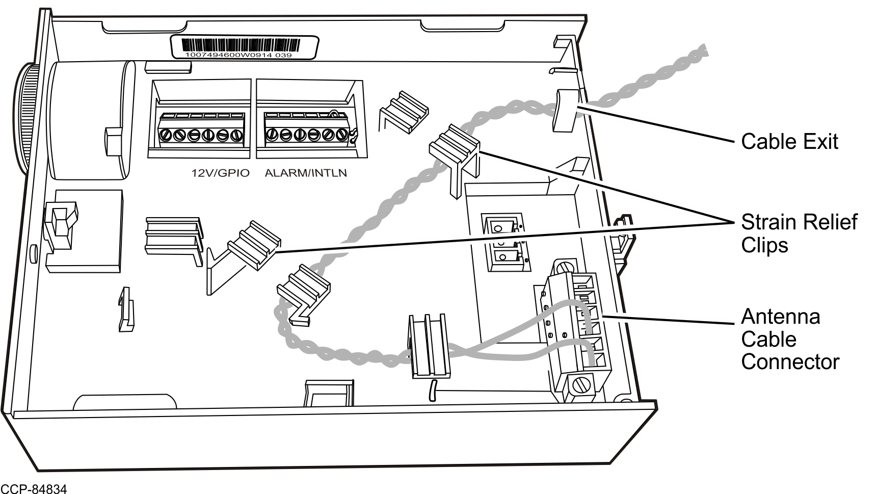
- Route the Antenna Cable through the Cable Exit.Note
Ensure to use the Strain Relief Clips to hold the cable in place.
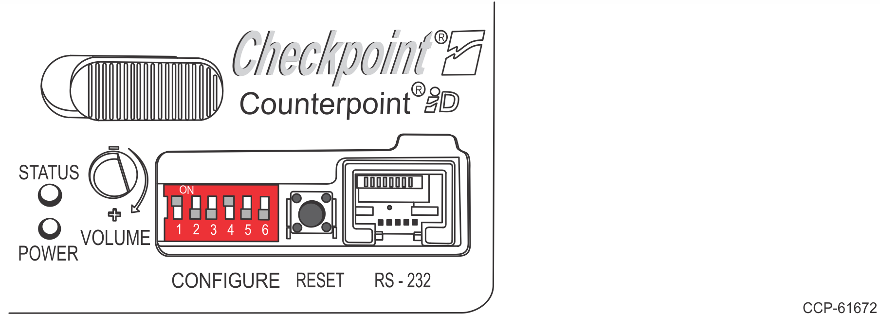
- Connect the R6 Checkpoint cable to the RS232 port of the Controller, as shown in the image below.
- Slide the cover onto the Controller and turn the thumbscrew to the right to secure the cover.
- Open the Pedestal Cabinet. For more information, refer to Opening the Pedestal Cabinet.
- Place the Checkpoint® controller inside the Pedestal Cabinet.
- Do the following:
- Secure the two (2) cables along the cable bundle using cable ties. Note
Ensure that the cables are isolated away from the other electronic cables.
- Continue to route the cables through the rear cable access hole and into the Scanner Bucket, as shown in the image below.
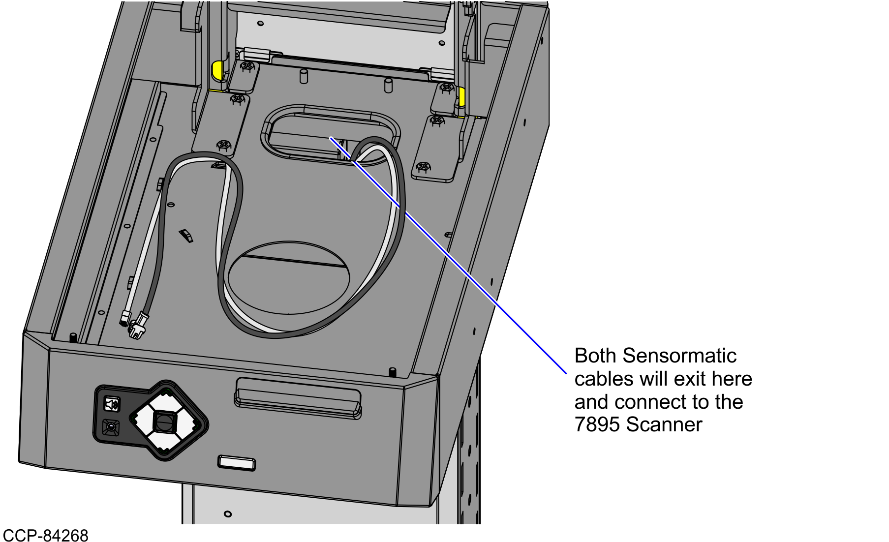
- Secure the two (2) cables along the cable bundle using cable ties.
- Do the following:
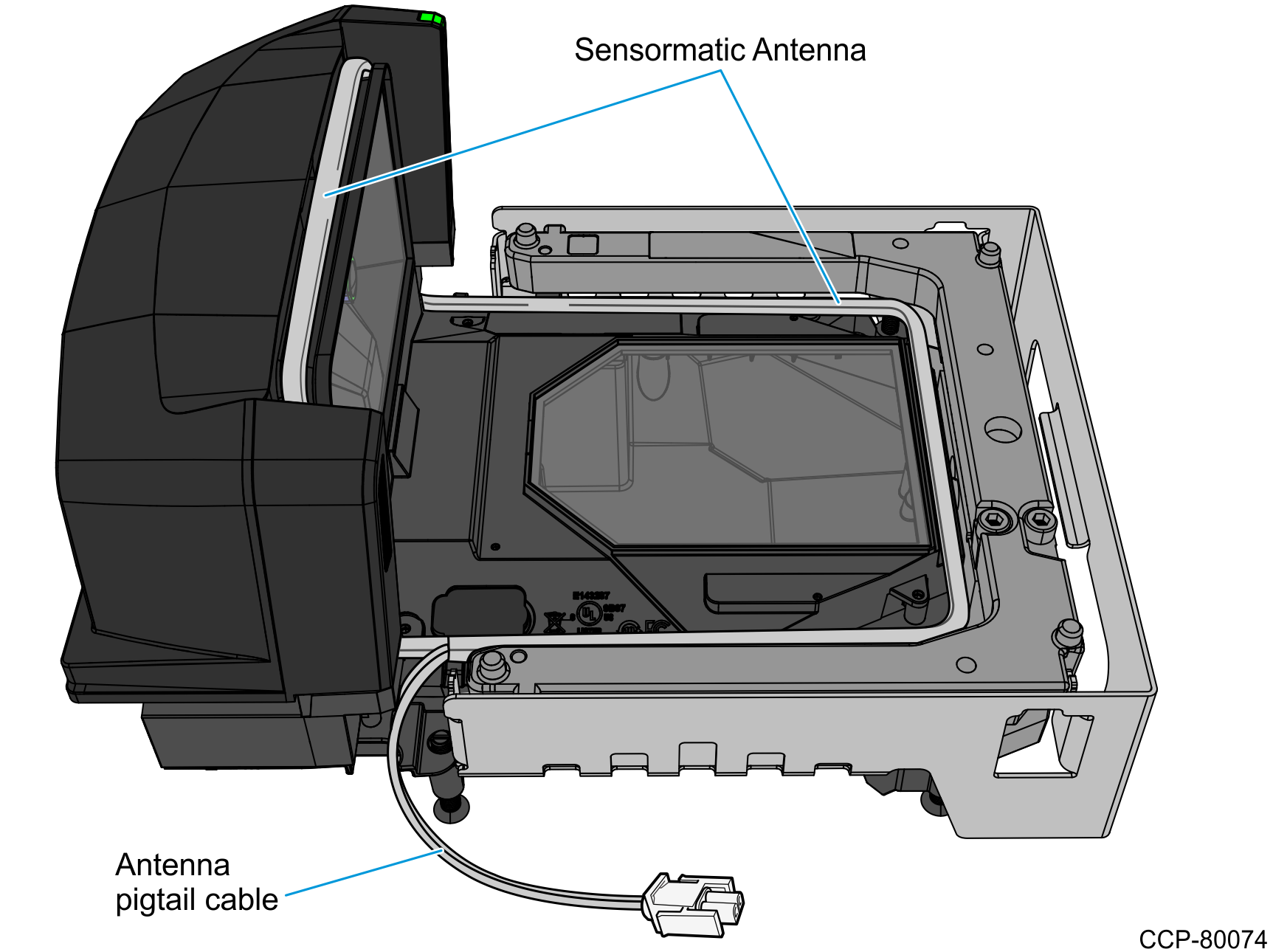
- Connect the Antenna cable to the Antenna Pigtail cable.
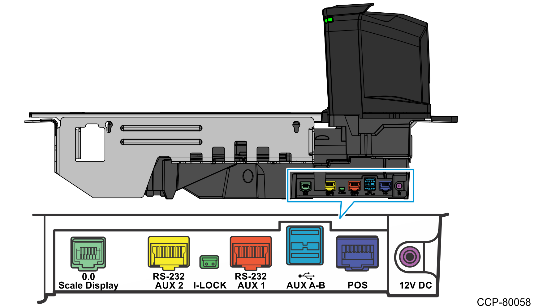
- Connect the 10-pin side of the interface cable to the RS-232 Aux 1 port of the Scanner/Scale.
- Connect the Antenna cable to the Antenna Pigtail cable.