Routing the cables
To route the cables in the NCR Voyix Self-Checkout (7360) Full Function unit, follow these steps:
If the XR7/XR7+ 24V+USB Port F is not available, the Interactive Status Light Cable is connected to the available 24V+USB Port J of the R6 I/O Box. Refer to the cable connection below.
| Interactive Status Light | Destination Connection (Location) |
|---|---|
| Interactive Status Light Cable |
|
| Unshielded Twisted Pair (UTP) Ethernet (LAN) Cable | PoE Switch |
- Route the Interactive Status Light Cable by doing either of the following, depending on the available port:
- XR7/XR7+ 24V+USB Port F
- From the Tower Frame pole duct, route the Interactive Status Light Cable to the back of the Tower Frame, as shown in the image below.
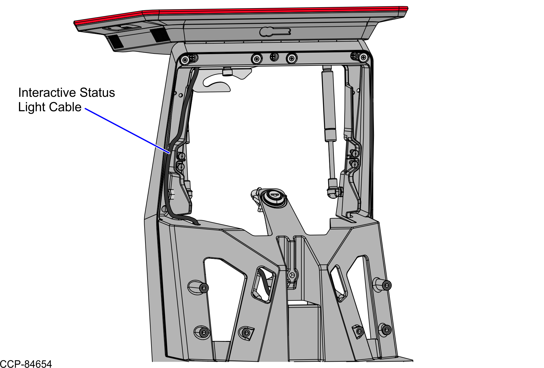
- Continue to route the cable to the Terminal Display through the Display Hinged Bracket and secure and secure it with a cable tie, as shown in the image below.Note
Apply enough slack to the cable so that it can move with the Terminal Display.
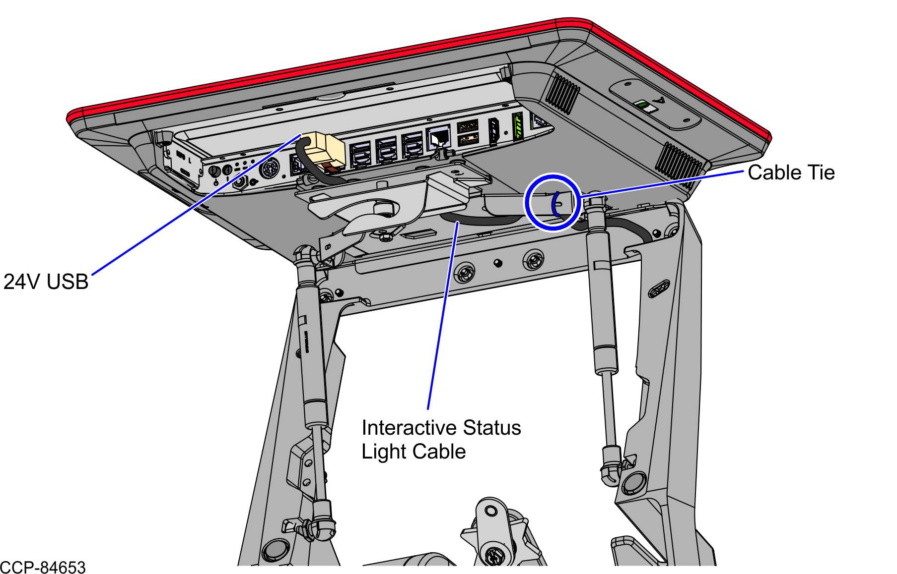
- Connect the cable to the XR7/XR7+ 24V+USB Port F.
- From the Tower Frame pole duct, route the Interactive Status Light Cable to the back of the Tower Frame, as shown in the image below.
- R6 I/O Box 24V+USB Port J
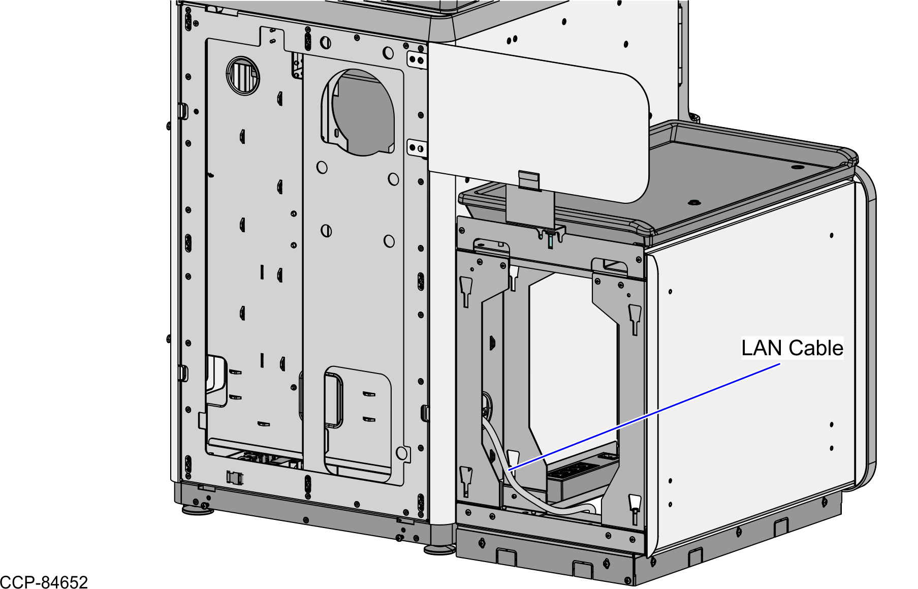
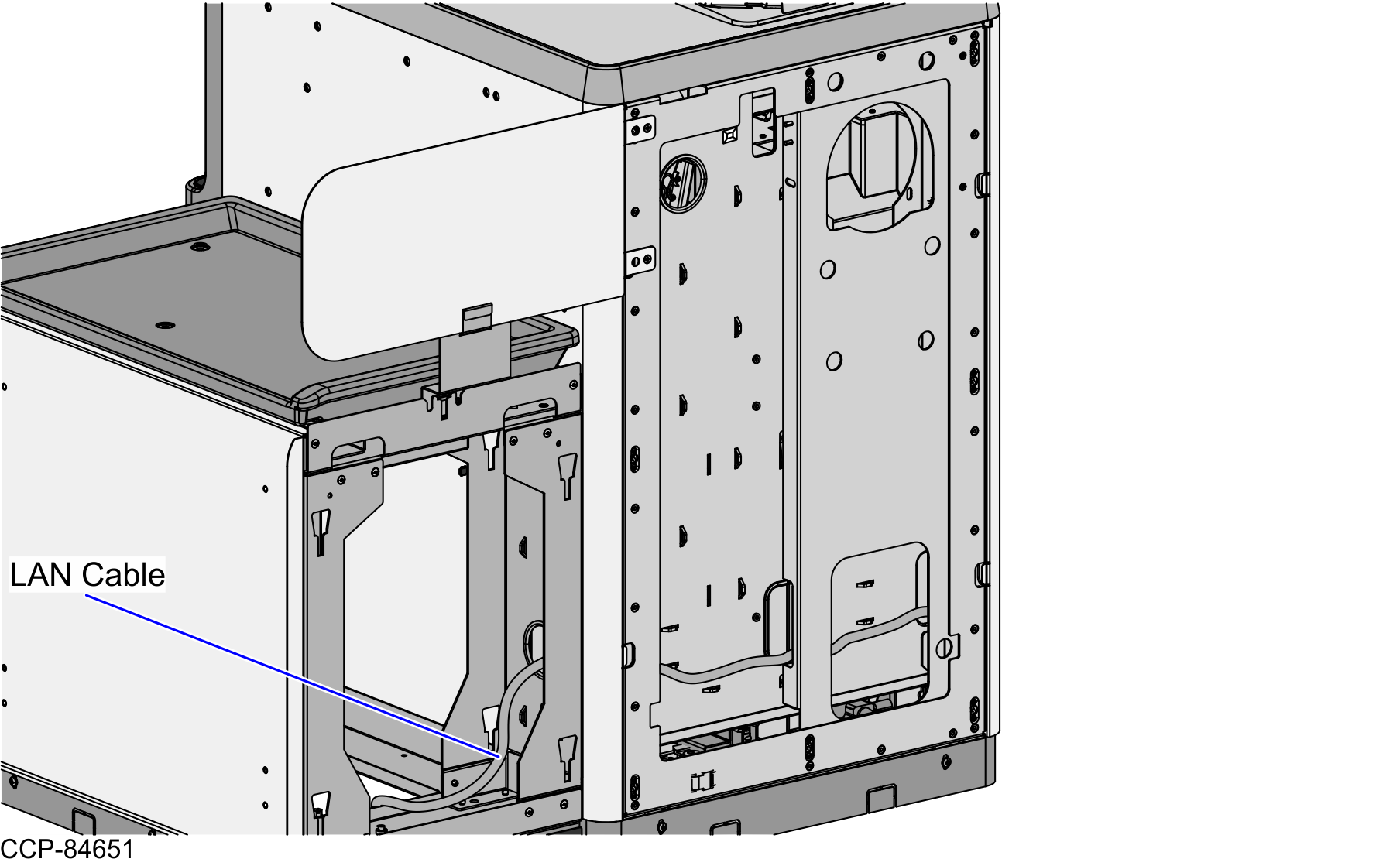
- From the Tower Frame pole duct, route the Interactive Status Light Cable and the LAN Cable down through the built-in hooks inside the Tower Frame.
- Route the cables down the Scanner Bucket floor and through the cable clamps.Note
Removal of the Scanner/Scale is required to gain access to the Scanner Bucket for cable routing.
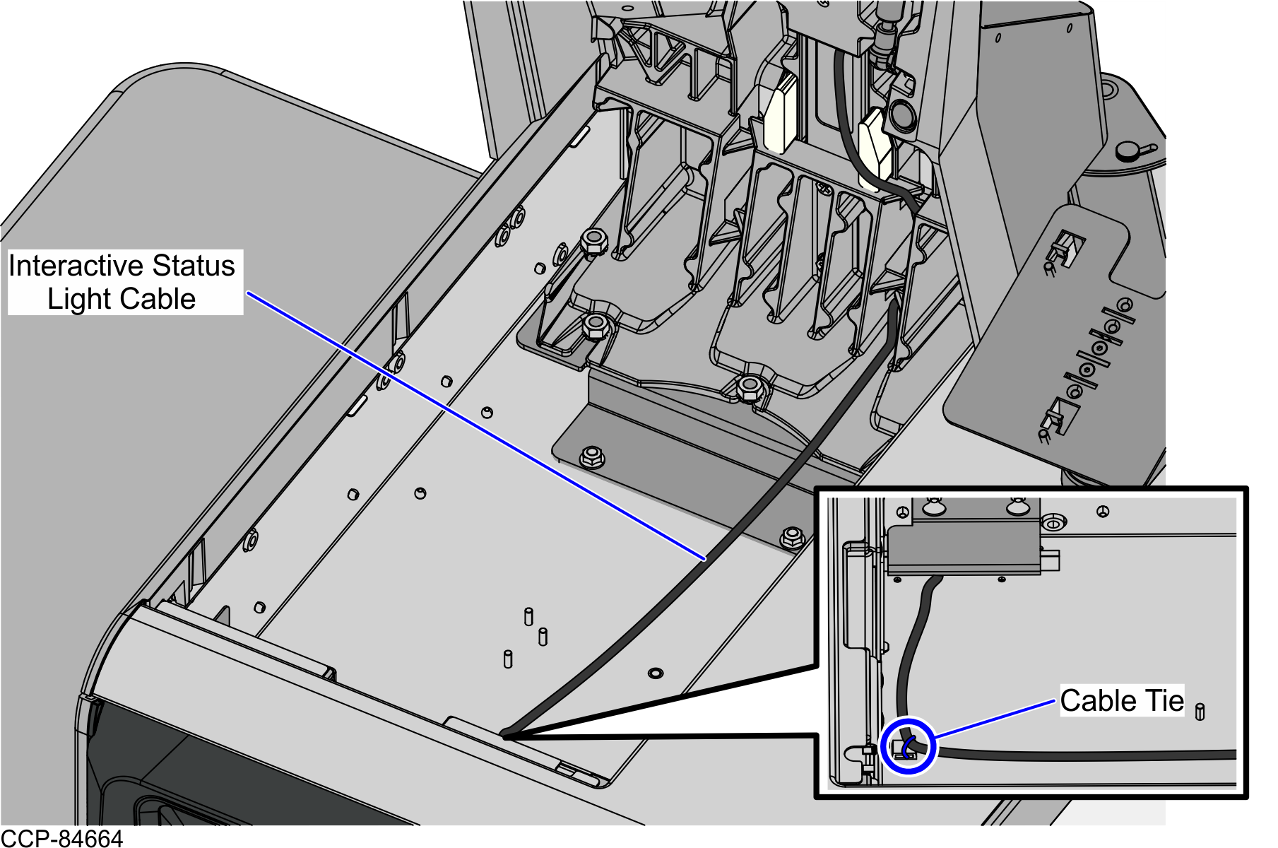
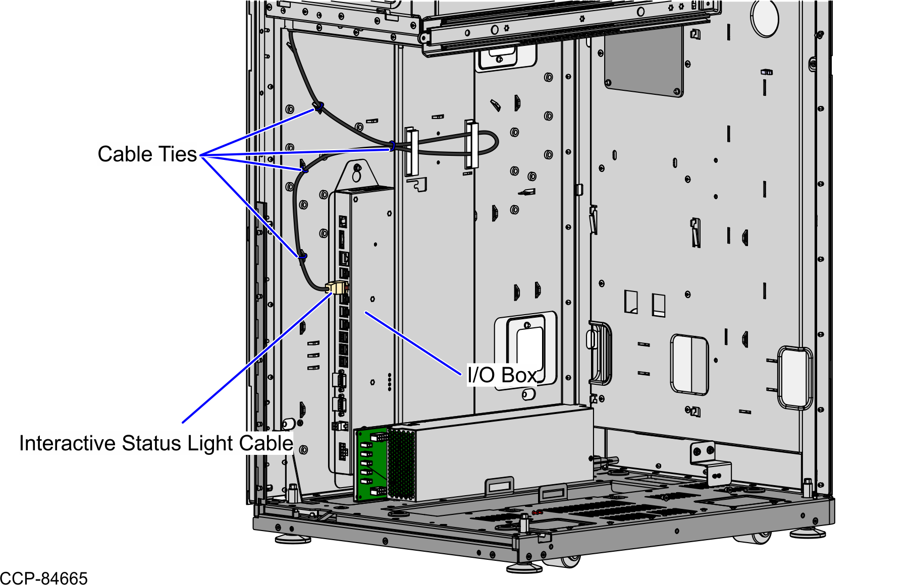
- From the corner cable access hole, route the Interactive Status Light Cable down the Core (Cabinet) wall and use cable ties to secure the cable on the bridge lances.
- Connect the cable to the 24V+USB Port J of the I/O Box.
- XR7/XR7+ 24V+USB Port F
- Route the LAN Cable. Depending on the configuration, refer to the following:
Routing the LAN Cable: No-Bag Unit
To route the LAN Cable, follow these steps:
- Do the following:
- From the Tower Frame pole duct, route the cable down through the built-in hooks inside the Tower Frame.
- Route the cable down the Scanner Bucket floor.Note
Removal of the Scanner/Scale is required to gain access to the Scanner Bucket for cable routing.
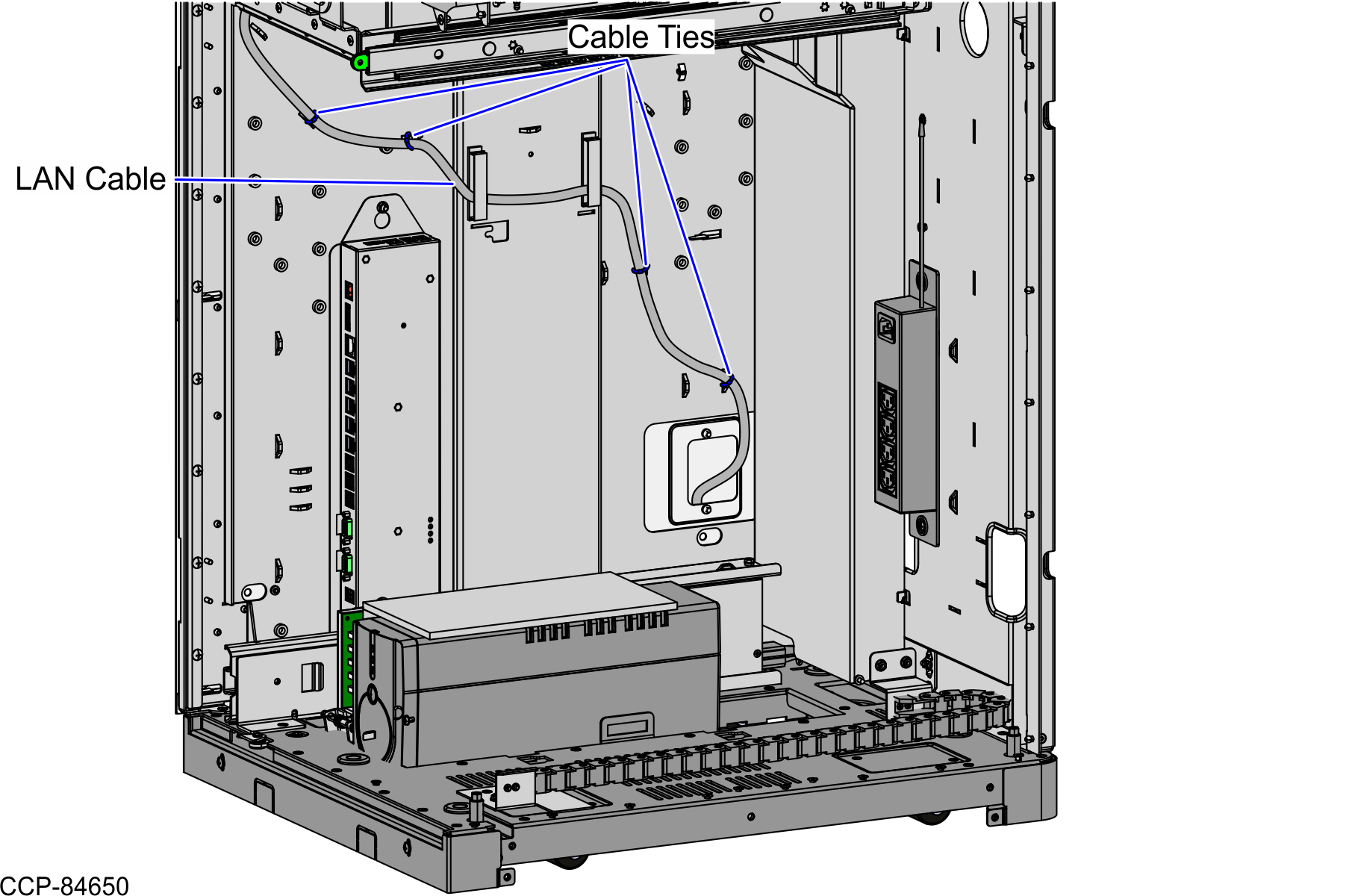
- Continue to route the cable down through the Corner Access Hole. Secure it to the anchor using a cable tie.
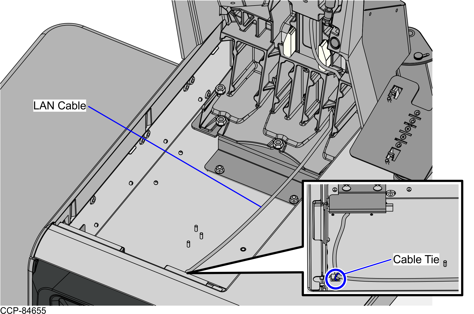
- From the corner cable access hole, route the cable down the Core Cabinet wall and down the bottom exit hole, as shown in the image below.Note
Pass the cable through cable clamps and secure the cable on the bridge lances using cable ties.
- Connect the cable to the PoE Switch.
Routing the LAN Cable: Left-Hand Unit
To route the LAN Cable, follow these steps:
- Do the following:
- From the Tower Frame pole duct, route the cable down through the built-in hooks inside the Tower Frame.
- Route the cable down the Scanner Bucket floor.Note
Removal of the Scanner/Scale is required to gain access to the Scanner Bucket for cable routing.
- Continue to route the cable down through the corner access hole. Secure it to the anchor using a cable tie.
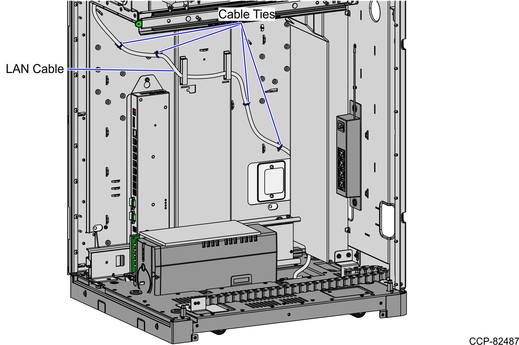
- From the corner cable access hole, route the cable down the Core Cabinet wall and into the Bagwell through the right side cable exit hole., as shown in the image below.Note
Pass the cable through cable clamps and secure the cable on the bridge lances using cable ties.
- Continue to route the cable out through the bottom cable exit hole and connect it to the PoE Switch.
Routing the LAN Cable: Right-Hand Unit
To route the LAN Cable, follow these steps:
- Do the following:
- From the Tower Frame pole duct, route the cable down through the built-in hooks inside the Tower Frame.
- Route the cable down the Scanner Bucket floor.Note
Removal of the Scanner/Scale is required to gain access to the Scanner Bucket for cable routing.
- Continue to route the cable down through the corner access hole. Secure it to the anchor using a cable tie.
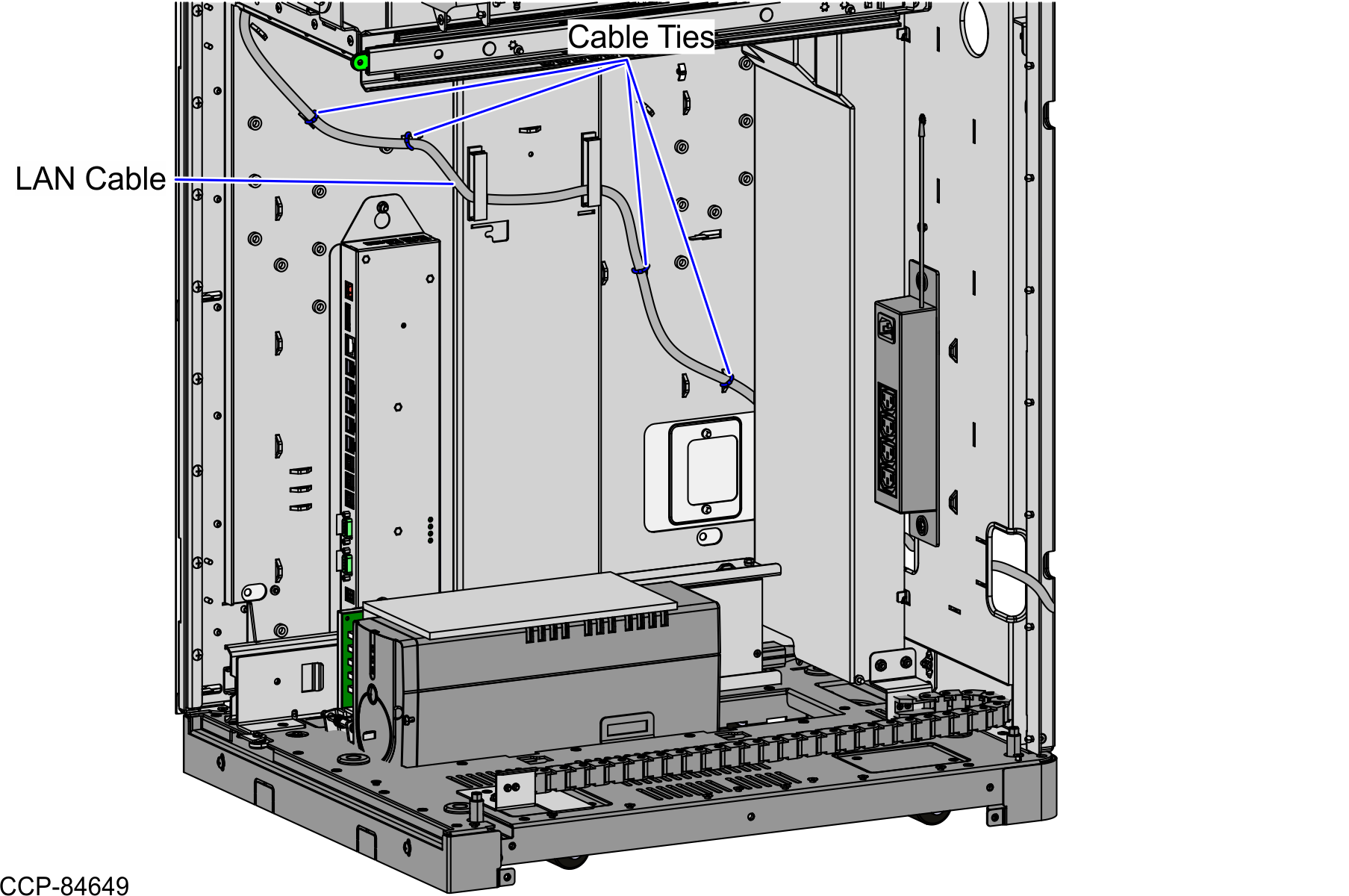
- From the corner cable access hole, route the cable down the Core Cabinet wall and into the Bagwell through the left side cable exit hole., as shown in the image below.Note
Pass the cable through cable clamps and secure the cable on the bridge lances using cable ties.
- Continue to route the cable out through the bottom cable exit hole and connect it to the PoE Switch.