Installation Procedure
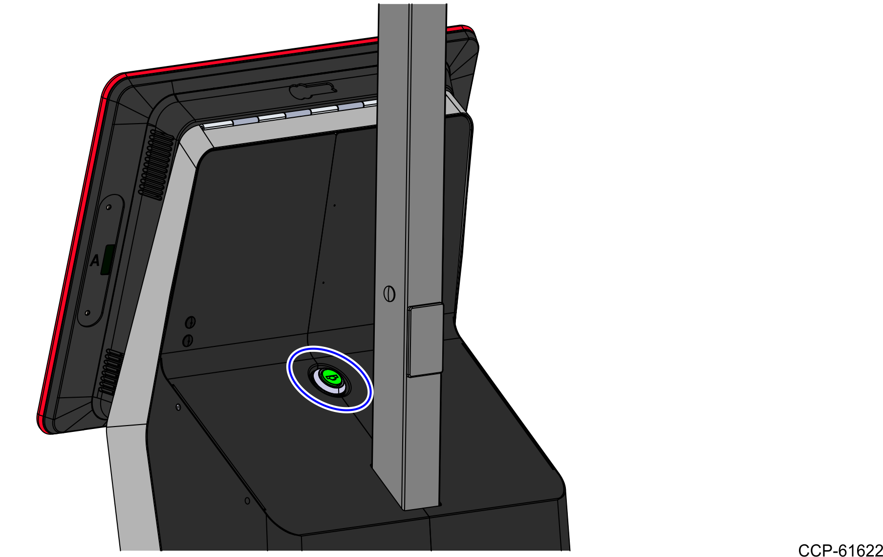
- Use a key to unlock the tower.
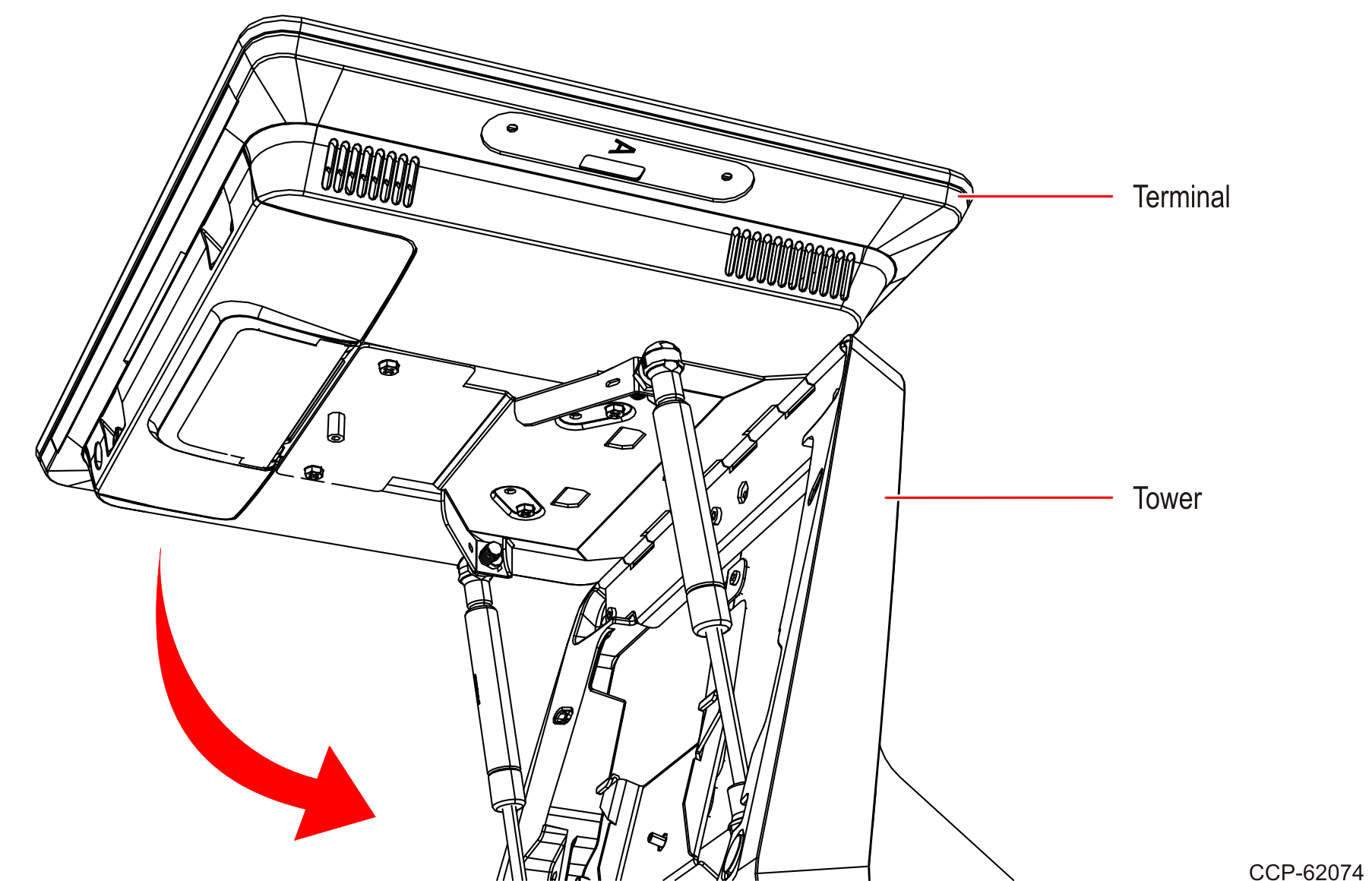
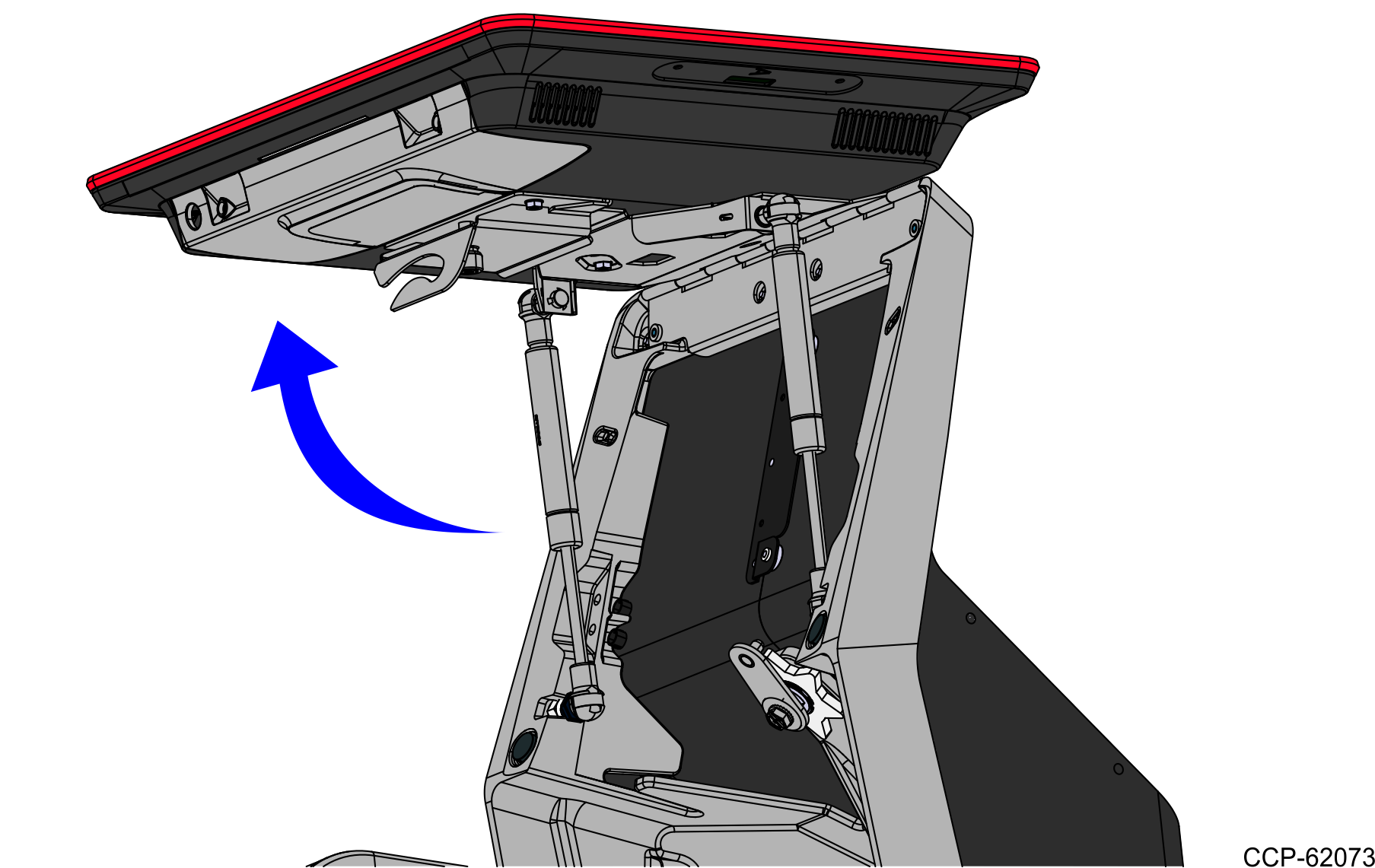
- Raise the terminal.
- If present, remove the Bi–Optic Scanner from the bucket area.
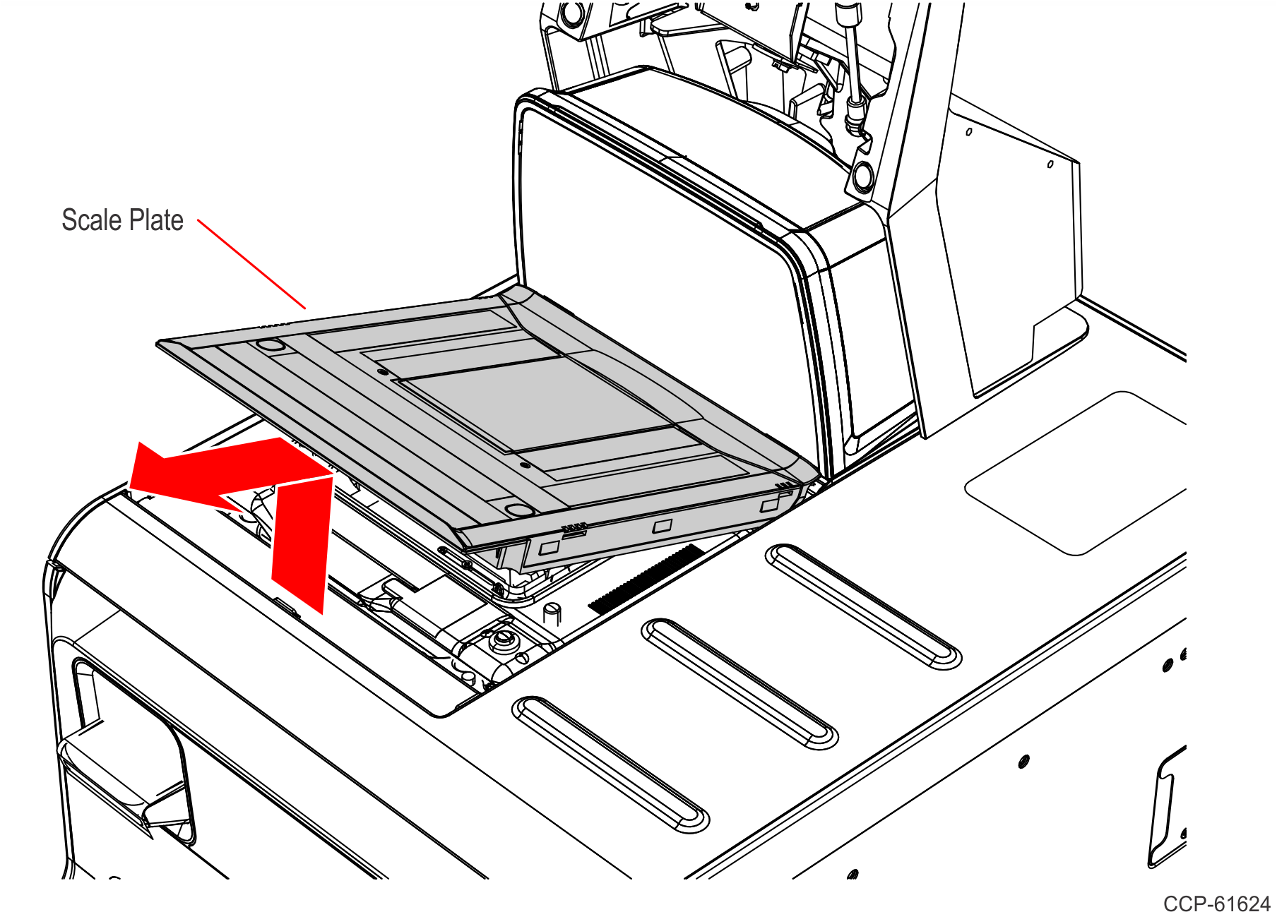
- Lift and remove the Scale Plate from the Scanner.
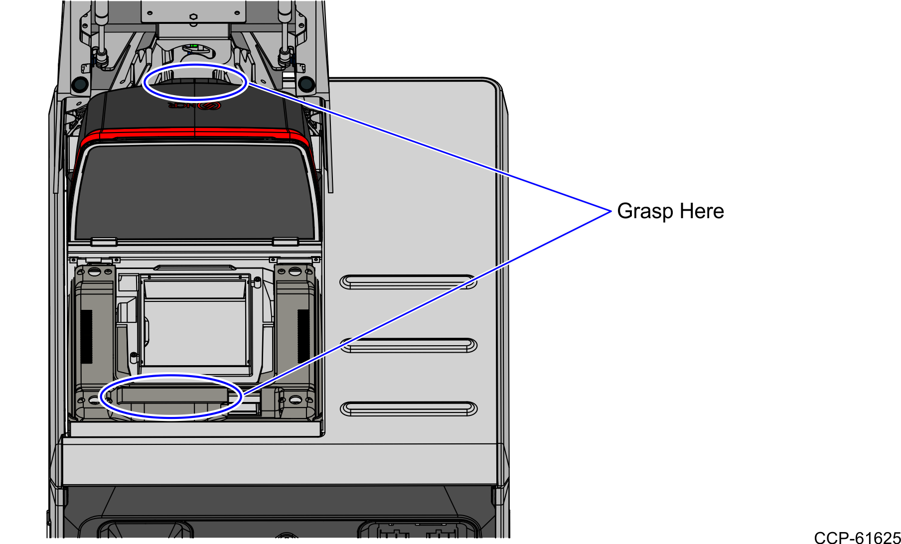
- Grasp the front of the Scanner and lift up, then grasp the back of the Scanner and slide the Scanner out of the bucket area.
- Disconnect all cables from the Scanner.
- Lift and remove the Scale Plate from the Scanner.
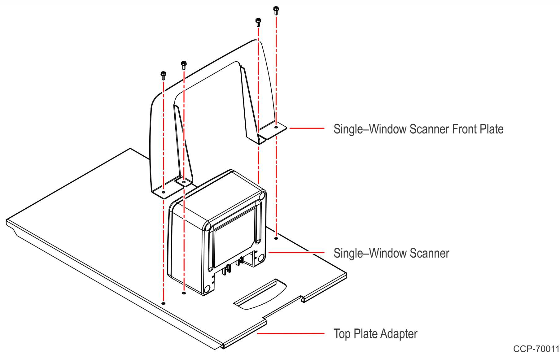
- Two Front Plates are included in the kit: No Scanner Front Plate and Single–Window Scanner Front Plate. Install the desired Front Plate to the Top Plate Adapter.
No Scanner Front Plate
- Install the No Scanner Front Plate on the Top Plate Adapter using four (4) M4 screws.

Single–Window Scanner Front Plate
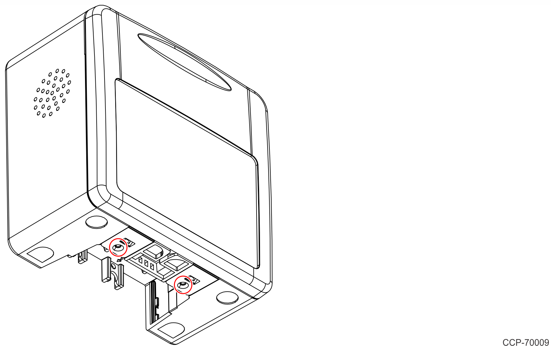
- If present, remove the two screws on the bottom of the Single–Window Scanner.
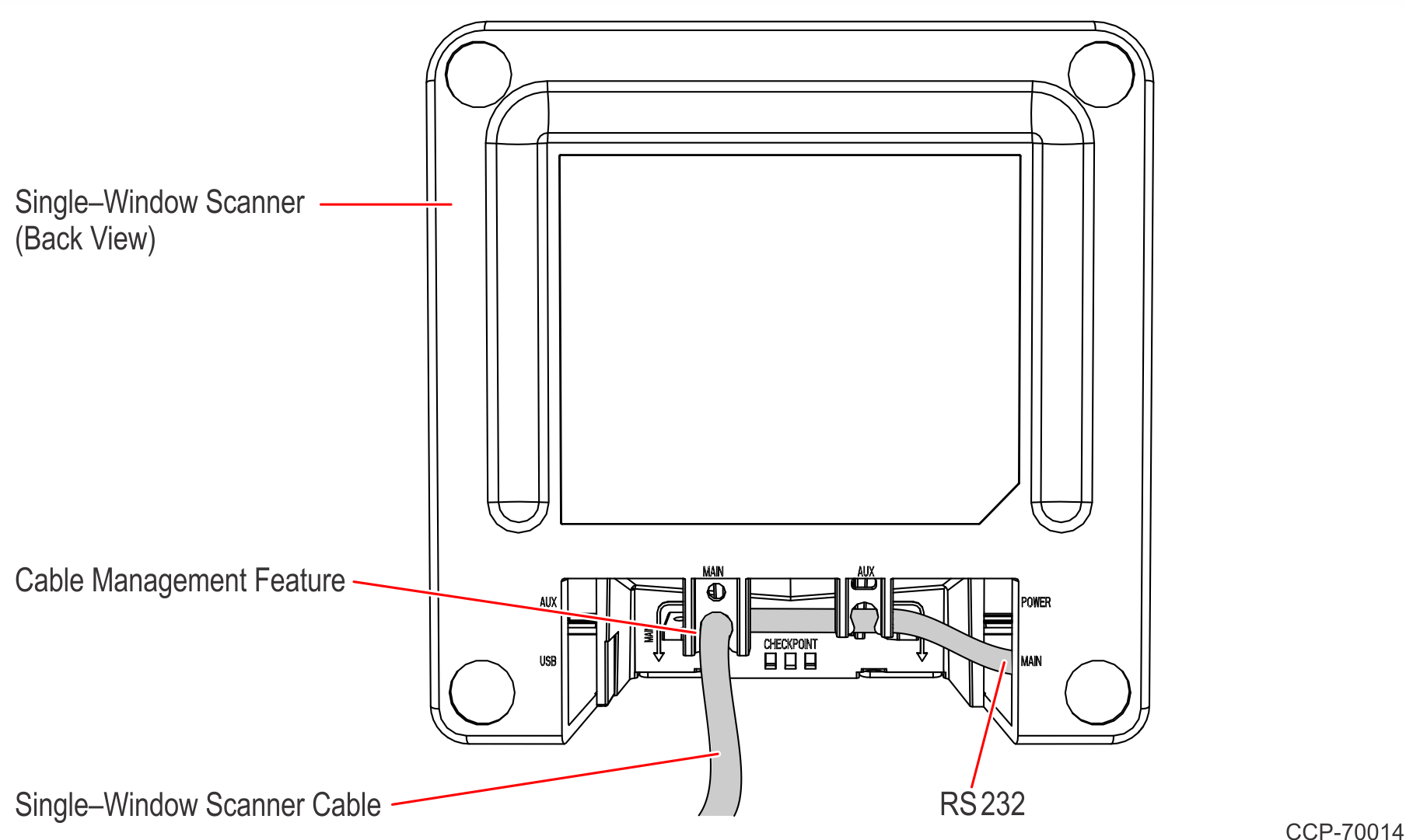
- Connect the RS232 end of the Single–Window Scanner Cable to the Single–Window Scanner and route it through the Cable Management Feature as shown.
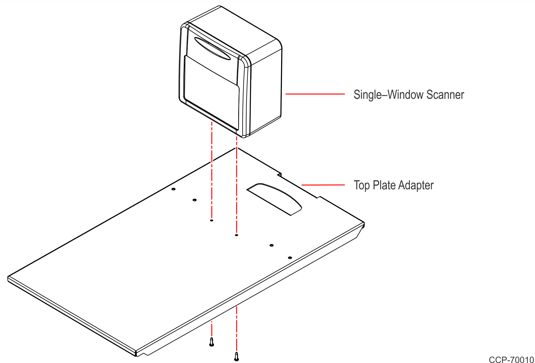
- Secure the Single–Window Scanner to the Top Plate Adapter using the two (2) Phillips screws included in the Kit.
- Install the Single–Window Scanner Front Plate on the Top Plate Adapter using four (4) M4 screws.
- Install the No Scanner Front Plate on the Top Plate Adapter using four (4) M4 screws.
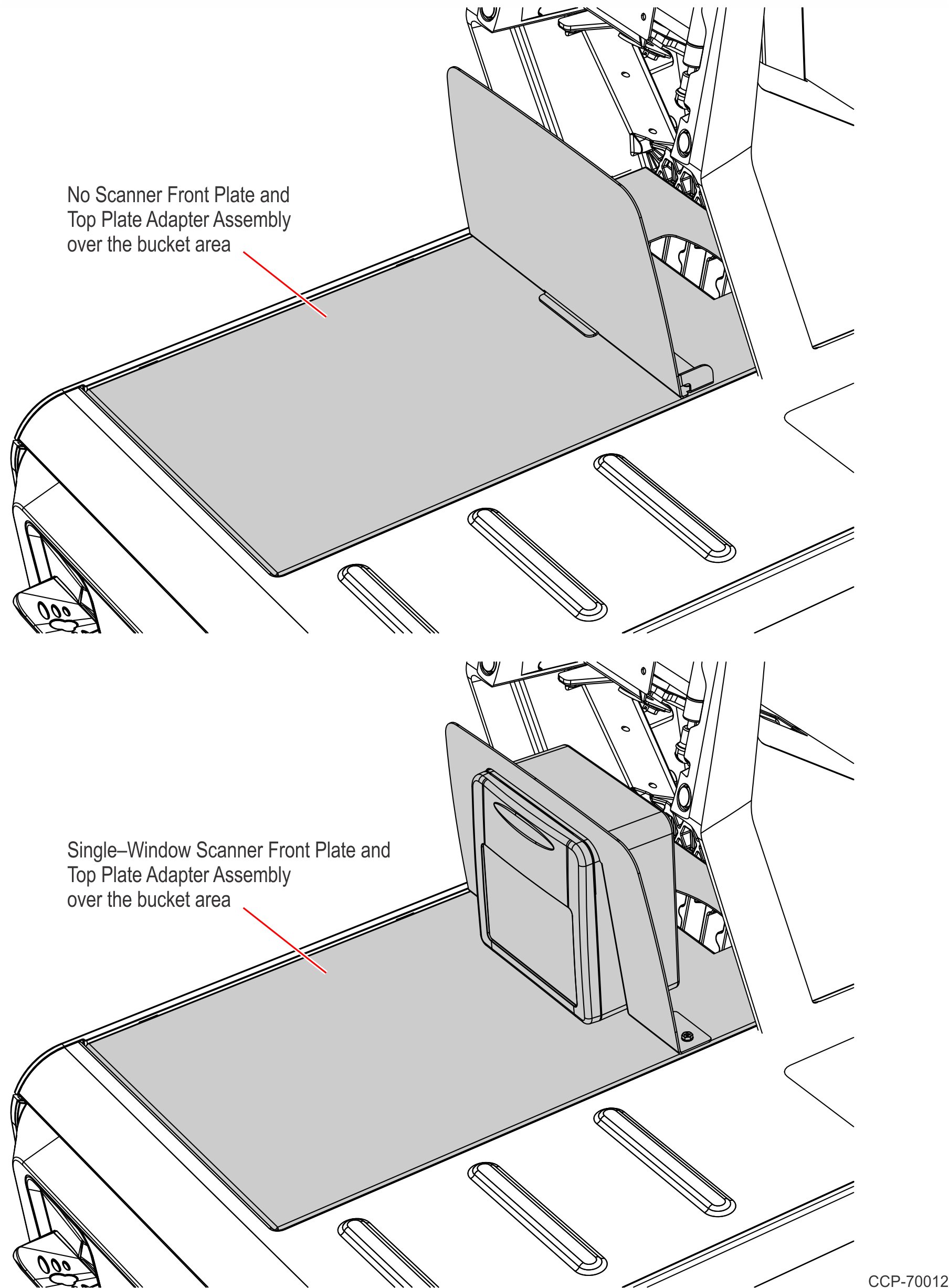
- Slide the Front Plate and Top Plate Adapter Assembly over the bucket area.
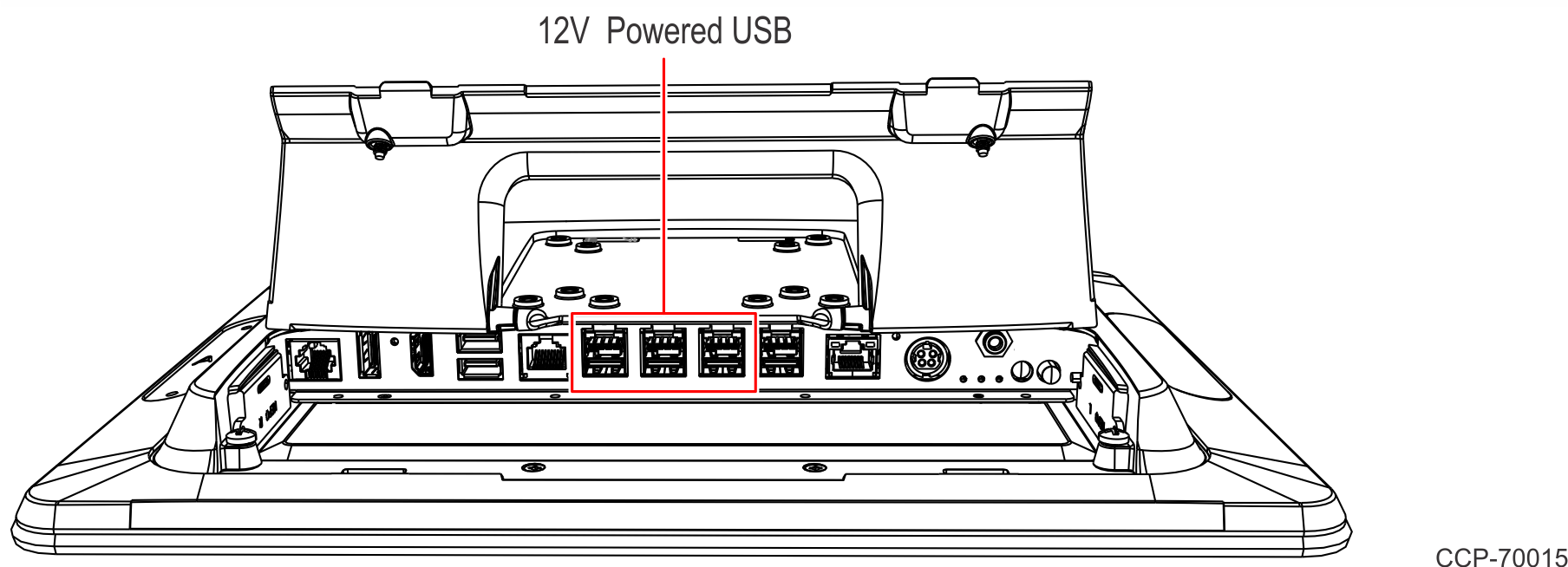
 Note
NoteIf Single–Window Scanner is present, connect the USB end of the Single–Window Scanner Cable to any available 12V Powered USB Port on the Terminal. Bundle the extra cable length.
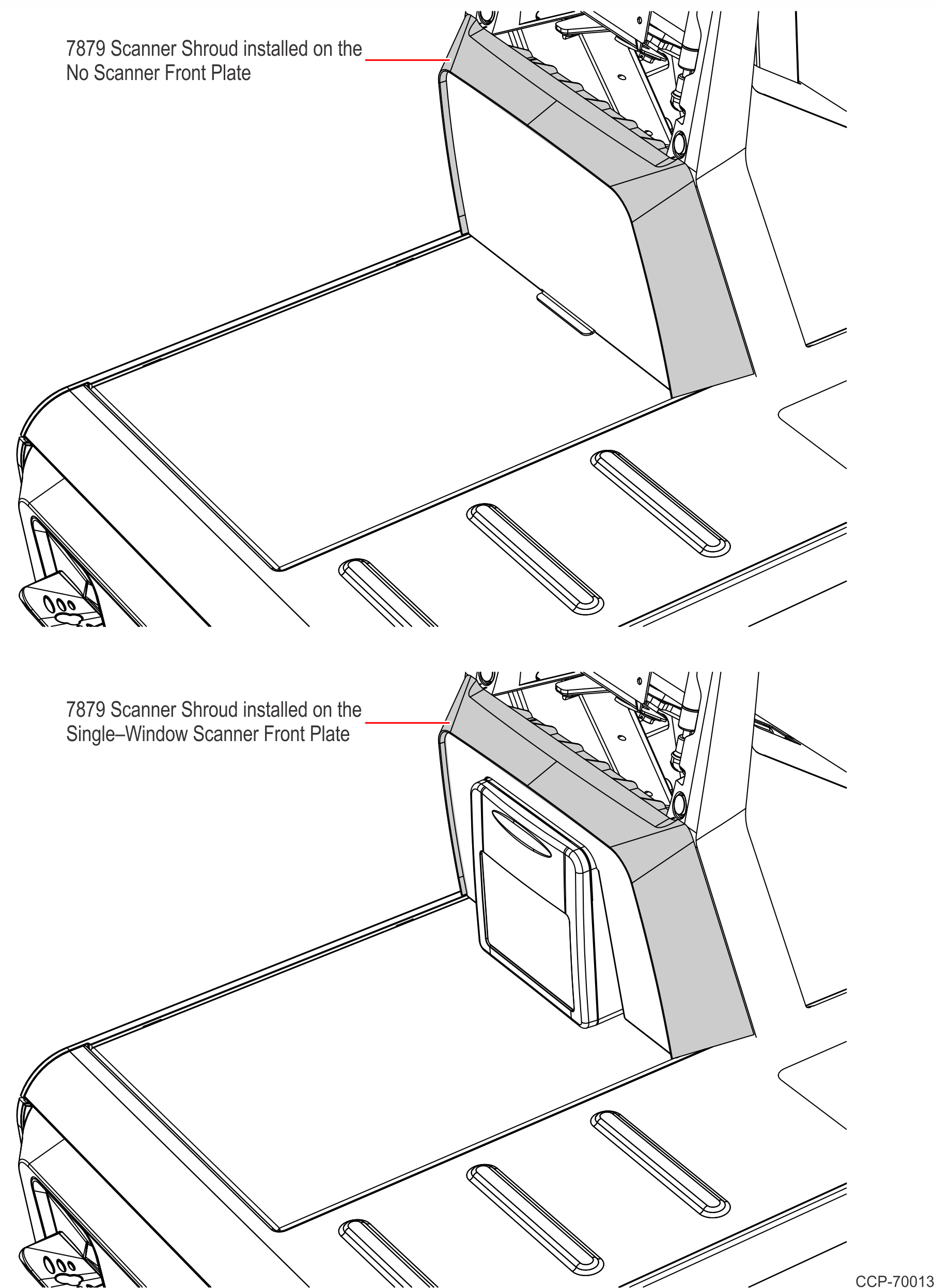
- Install the 7879 Scanner Shroud on the Front Plate. The Shroud is rubber and can flex into place.
- Lower the terminal then lock the tower.