Adjusting Tri-Light/Lane Light Jumper Settings to +24V
The R6 Tri-Light/Lane Light is powered by +24Vdc through the 7360 I/O Box. To adjust the jumper settings, follow these steps:
1.Remove all cables from the 7360 I/O Box.
Tip: Mark all cables as to where they are connected to easily reconnect them.
2.Detach the I/O Box from the SelfServ Checkout unit by removing one nut securing the I/O Box to the I/O Box Mounting Plate.
3.Do the following:
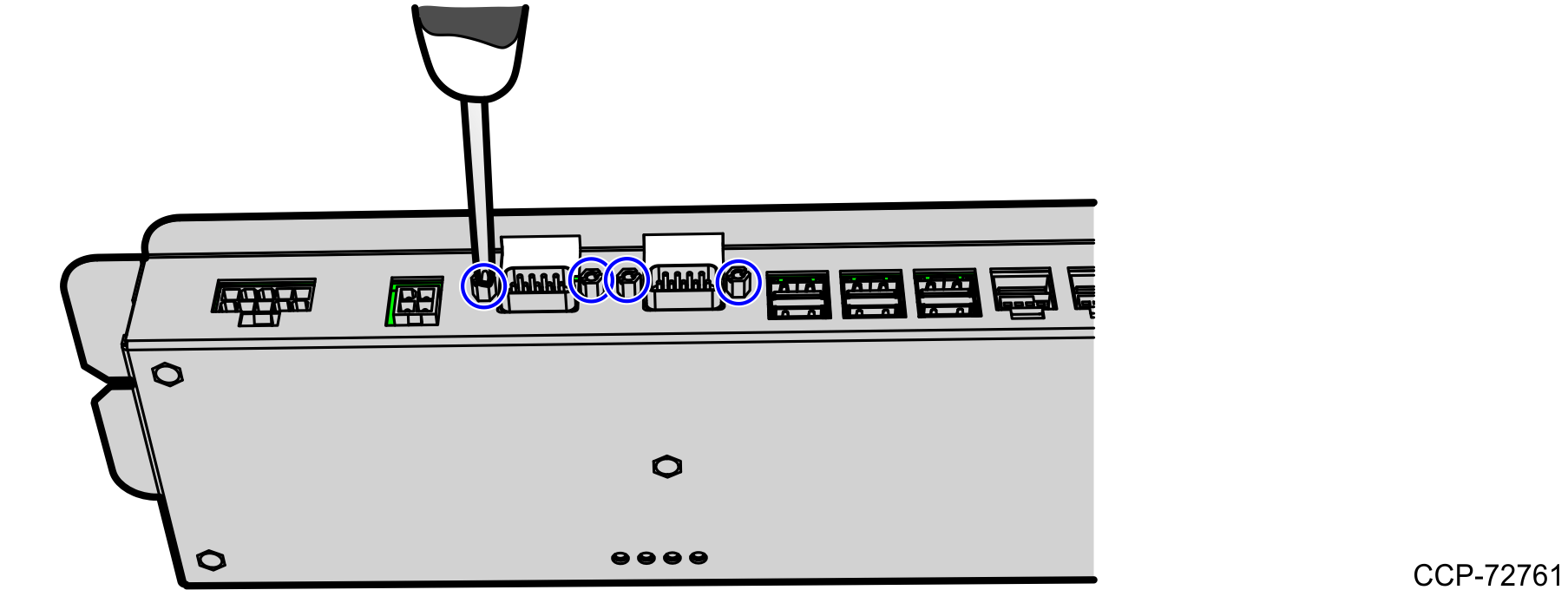
•Remove four screws securing two RS232 Ports to the I/O Box.
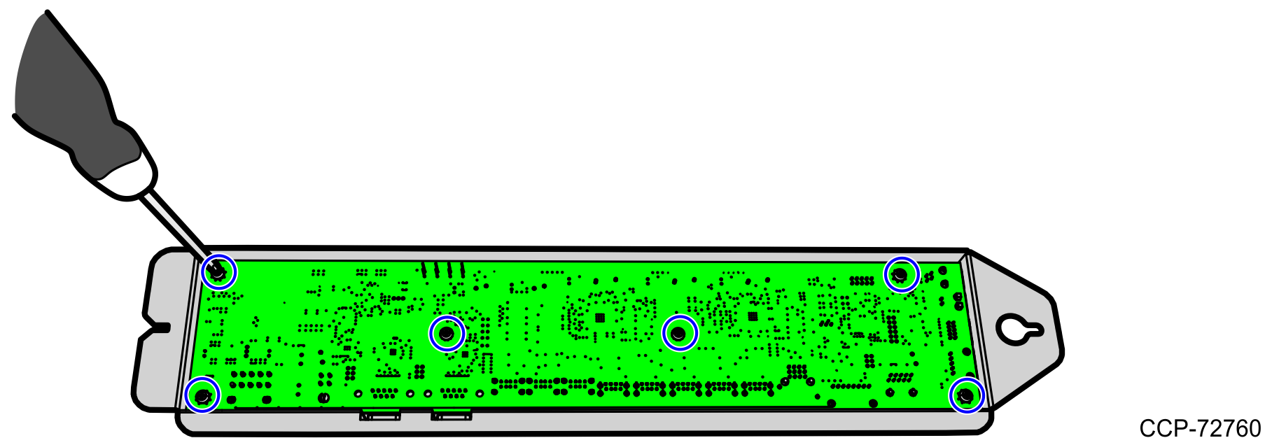
•Remove six screws securing the I/O Board to the I/O Box.
•Remove the I/O Board from the I/O Box and then place it on a flat surface.
4.On the I/O Board, remove the jumper and set it on Pin 5 and Pin 6 as shown in the image below.
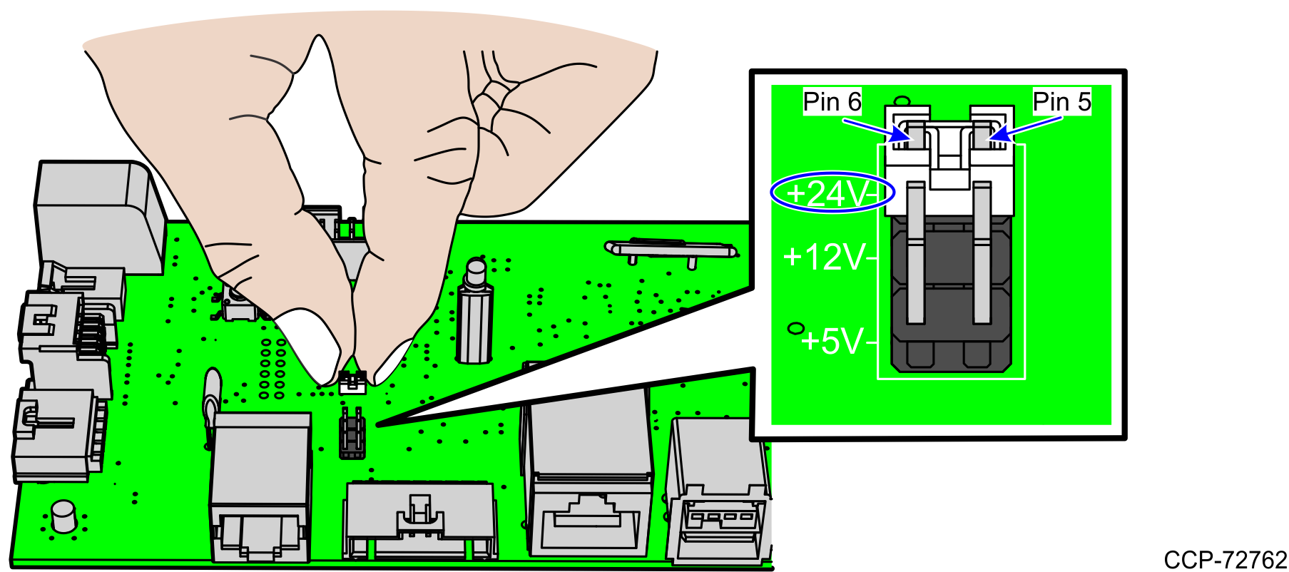
Each jumper setting corresponds to a specific Tri-Light/Lane Light.
•+24Vdc—Powers the R6 Tri-Light/Lane Light.
•+12Vdc—Powers the R6 Cylindrical Tri-Light/Lane Light.
•+5Vdc—Powers the 7350 (R5) Tri-Light/Lane Light.
5.Do the following:
•Secure the I/O Board to the I/O Box using six screws.
•Secure two RS232 Ports to the I/O Box using four screws.
6.Install the I/O Box to the SelfServ Checkout unit by securing it to the I/O Box Mounting Plate using one nut.