Routing Cables for No-Bag unit
These are additional steps in routing cables when upgrading a No-Bag unit to a 1-Bag unit:
Note: Use the new USB Power Cable. Route the USB Power Cable to the E-Box first before installing new Bagwell.
1.Unlock and open the upper Cabinet Door.
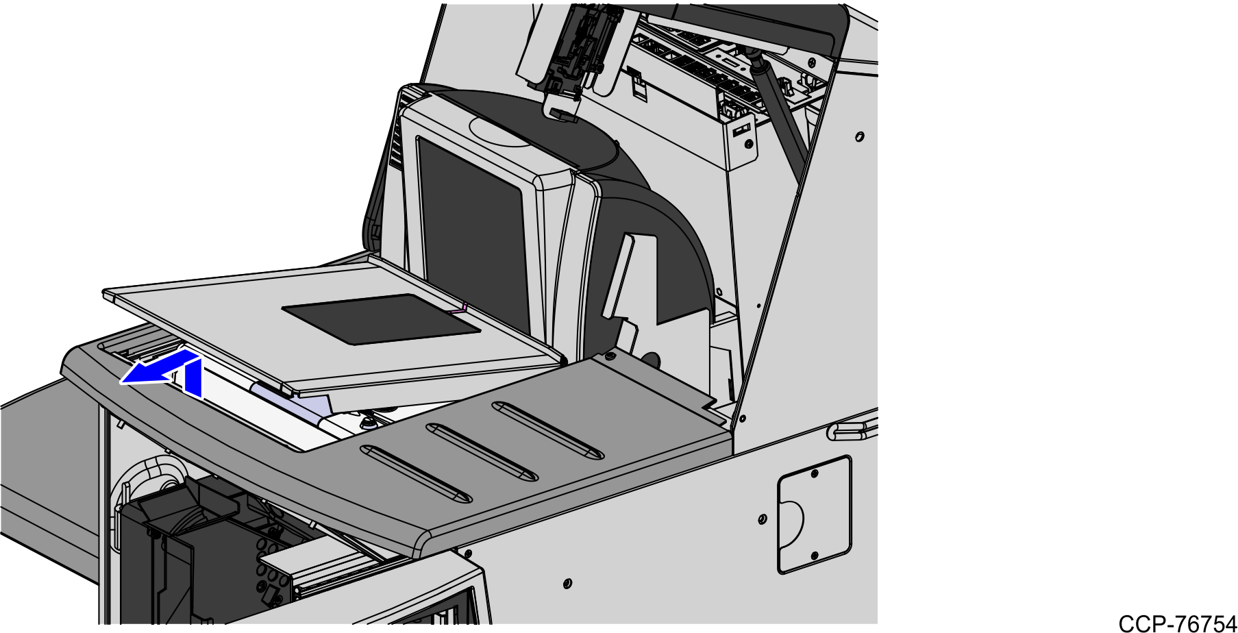
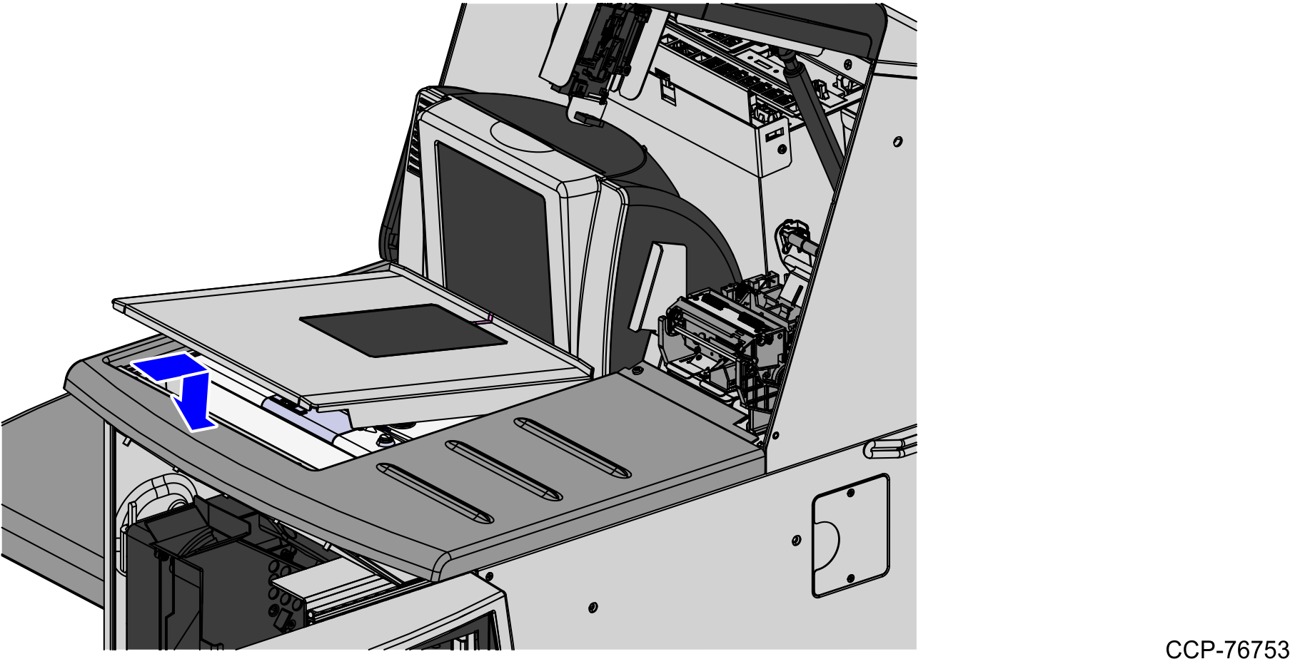
2.Lift the Scale Plate from the Scanner.
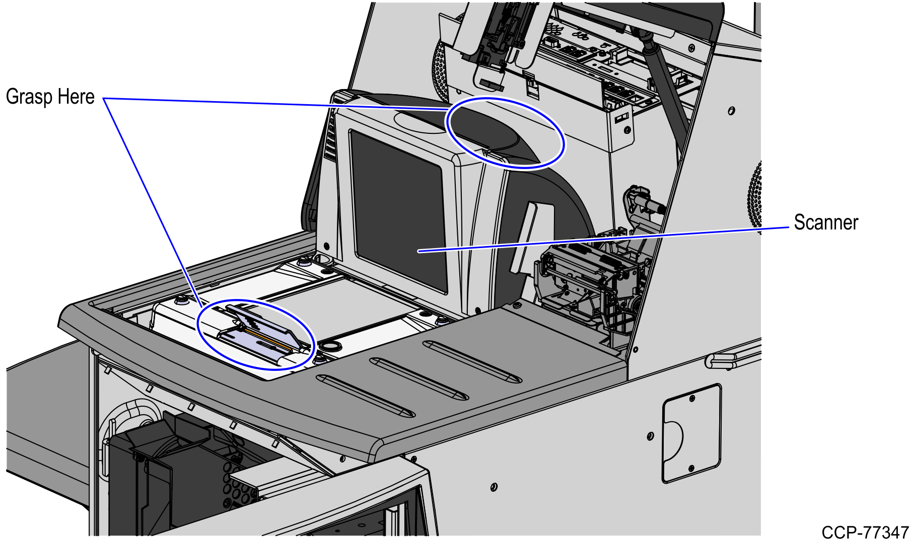
3.Do the following to remove the Scanner/Scale from the scanner bucket area.
a.Grasp the front of the Scanner and lift up.
b.Grasp the back of the Scanner and slide scanner out of the bucket area.
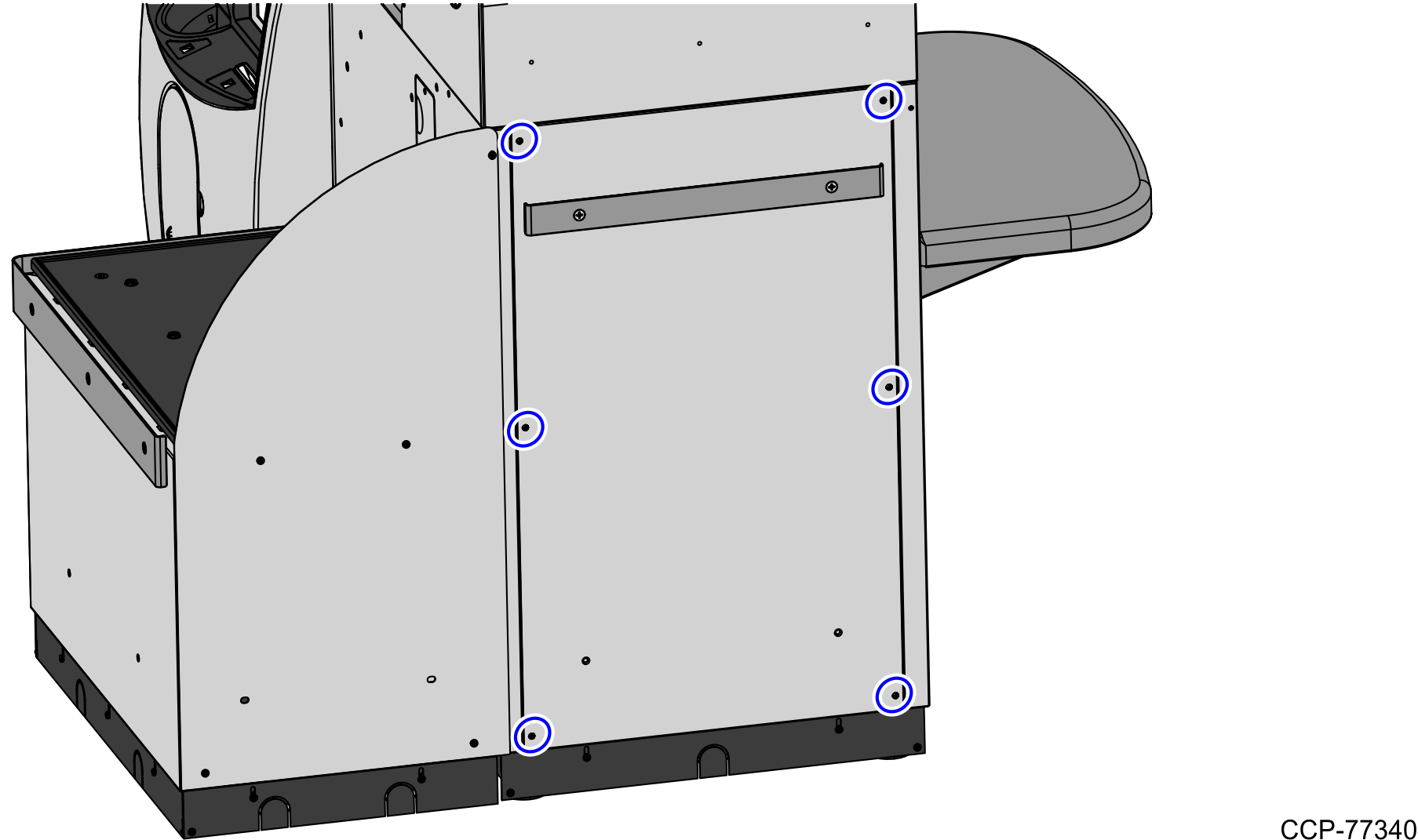
4.Detach the rear Core panel by removing six (6) screws to access the main cable bundle and Power Strip.
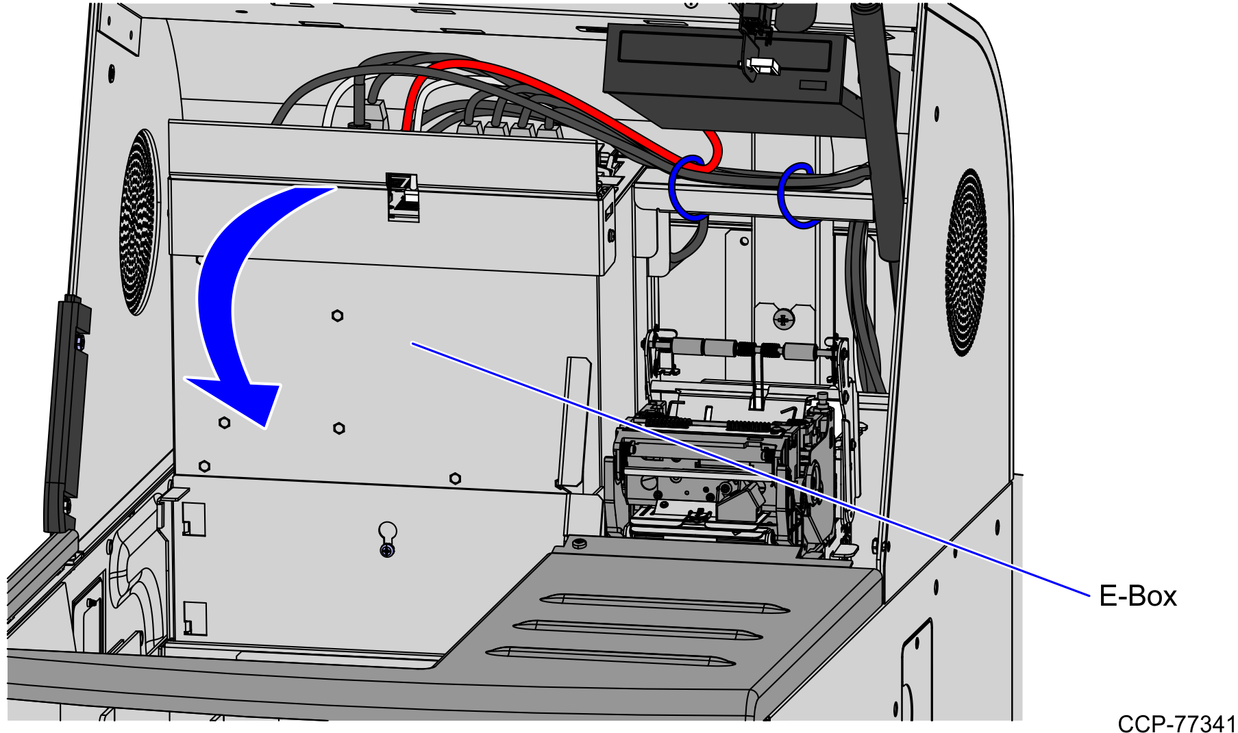
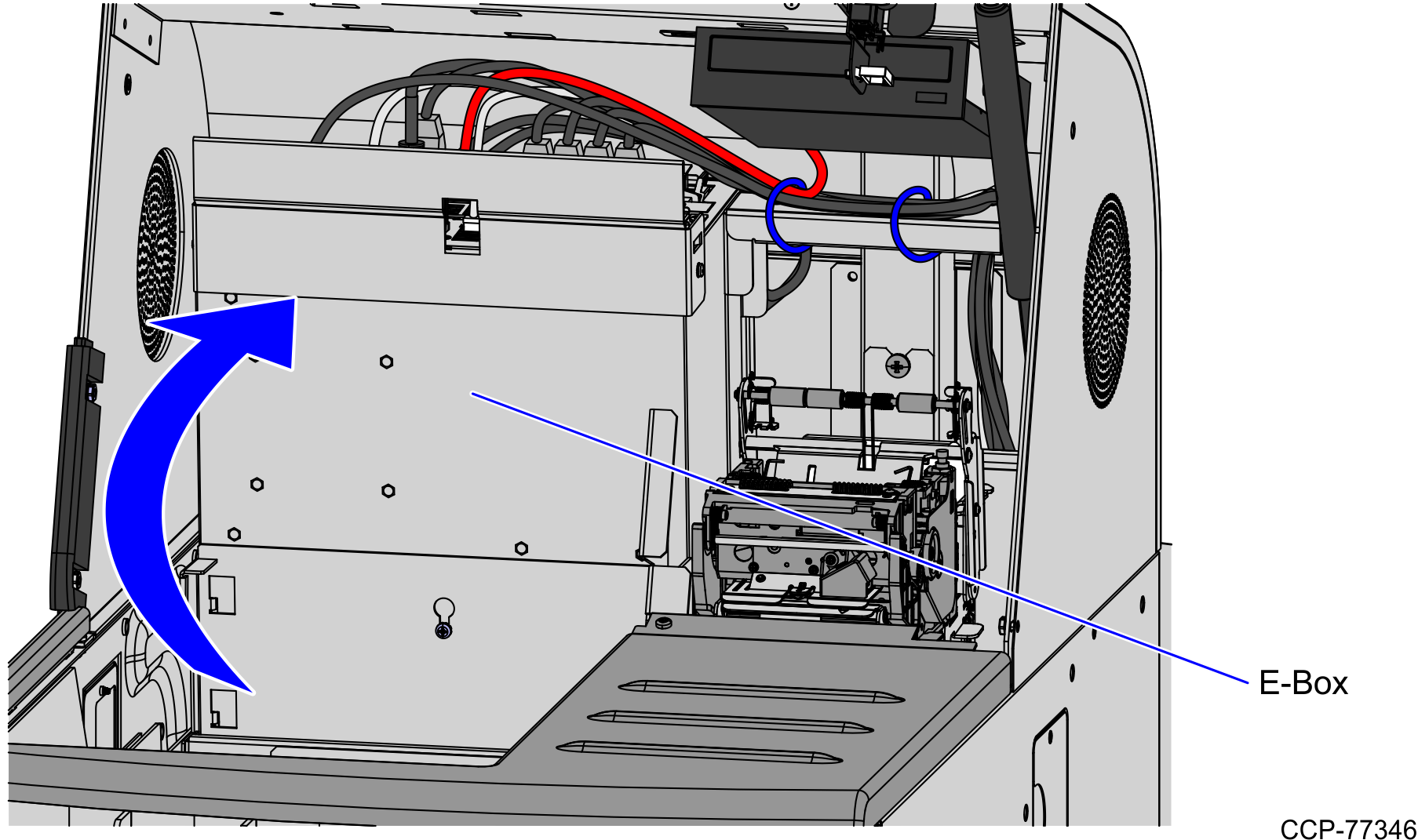
5.Tilt the E-Box Bracket forward to easily access the cables.
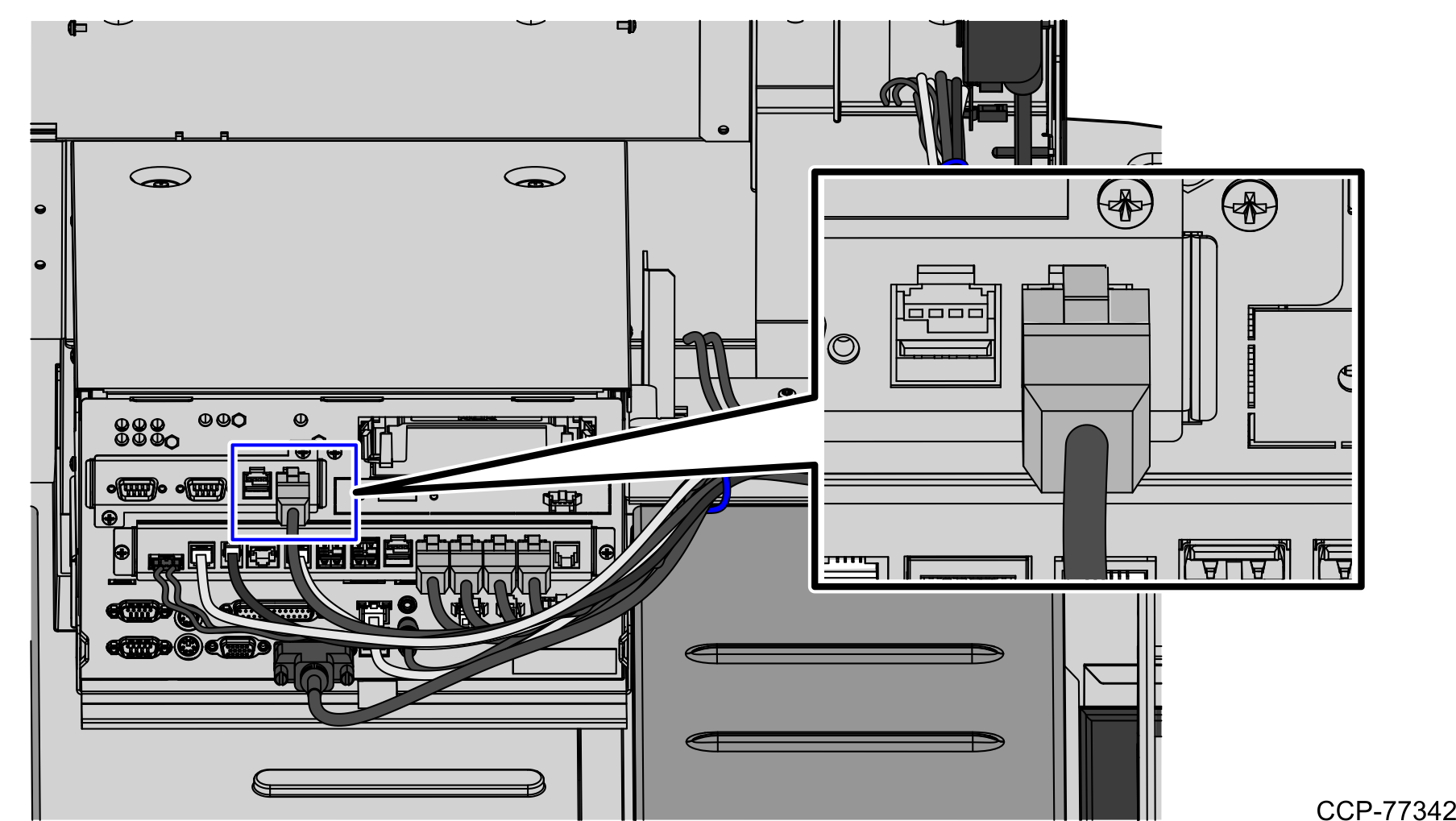
6.Unplug the pre-installed USB Power Cable from the Scale Controller in the new Bagwell and plug host connector to the USB M Port of the E-Box.
7.Tie the Scale Controller Cable to the main bundle by using six (6) cable ties.
Note: Secure the main cable to the E-Box with the first two (2) cable ties.
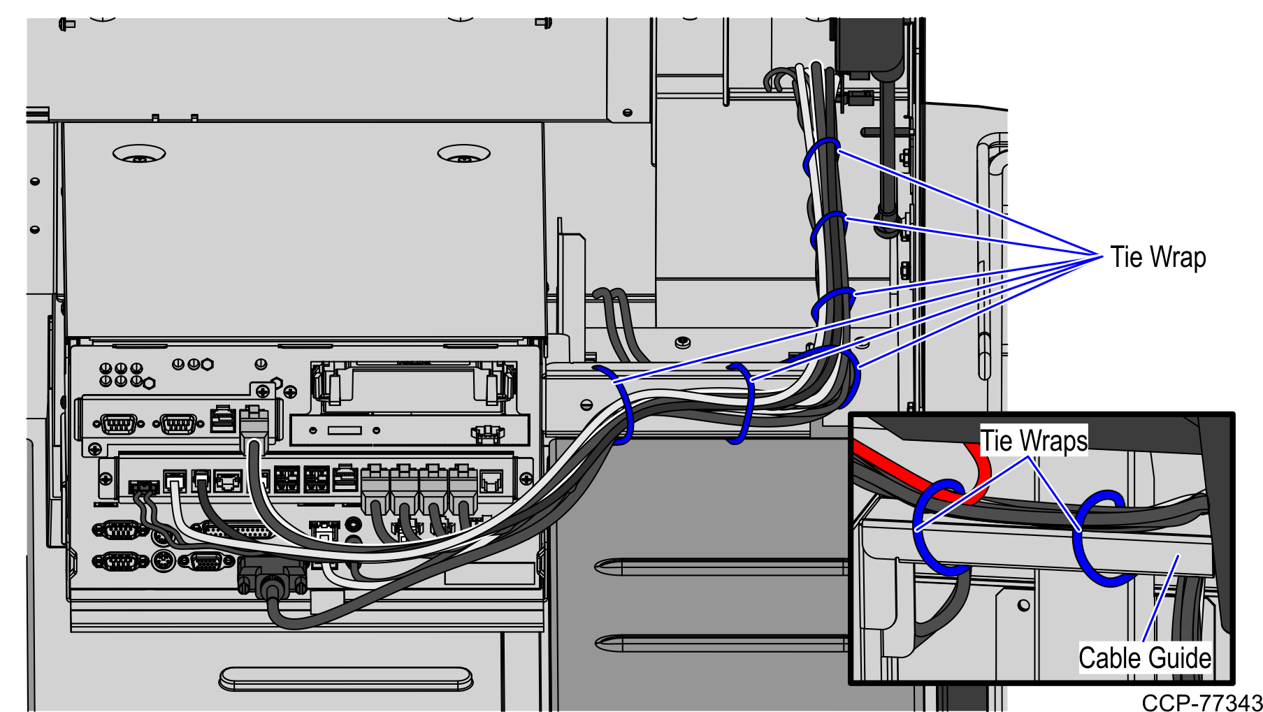
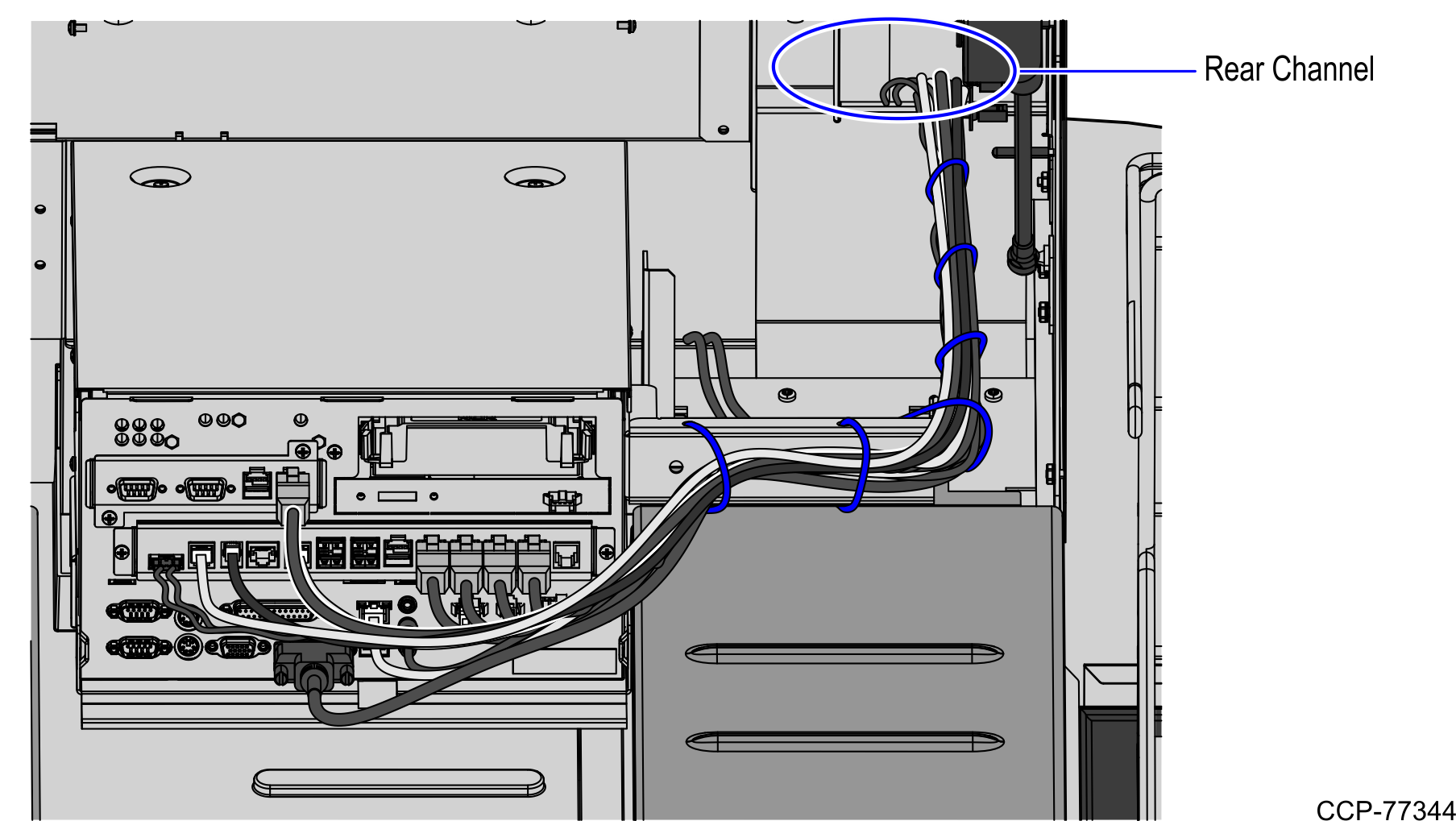
8.Continue routing the cable down the back of the Receipt Printer, as shown in the image below. Push all the cable slack to the rear of the Core.
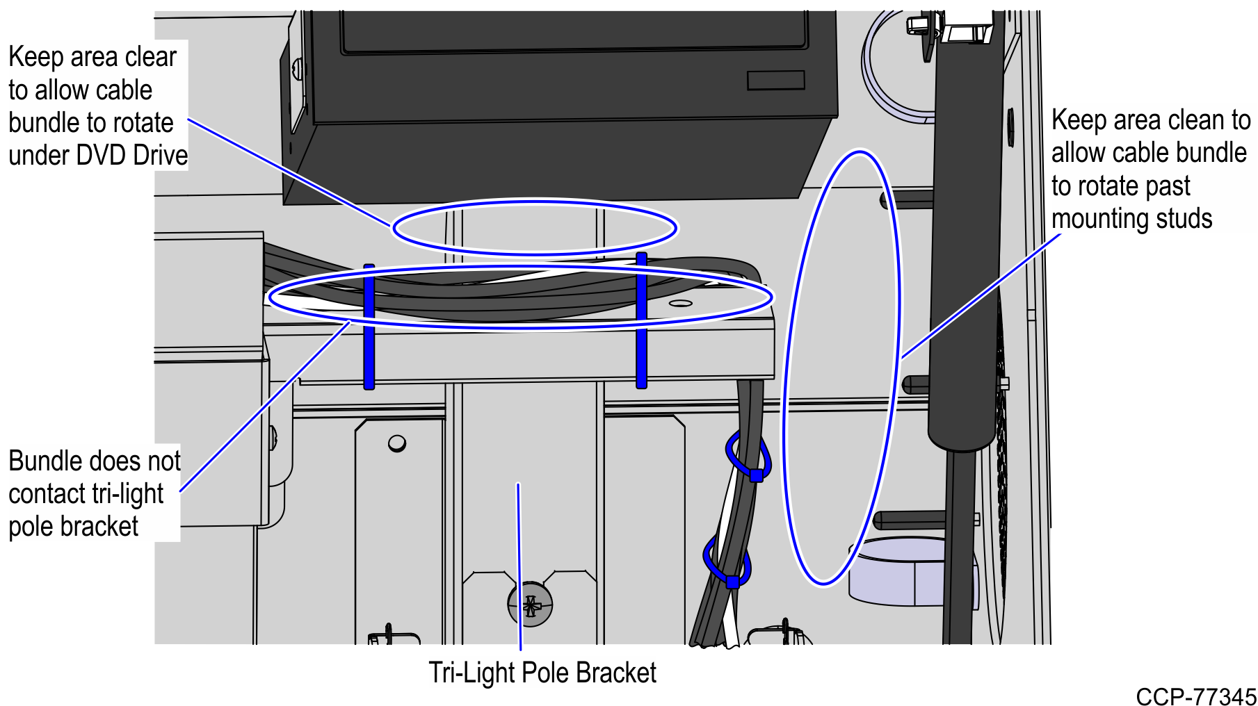
9.Ensure that the cable bundle is not in contact with the Tri-Light pole bracket, DVD Drive, and ventilation fan studs when the E-Box is tilted from Up to Down positions as shown in the image below.
10.Rotate the E-Box back up. Help feed the cables down the back of the Receipt Printer to ensure that the cables are not tangled when the E-Box is rotated.
11.Install the Scanner/Scale. To install the Scanner/Scale, follow these steps:
a.Grasp the Scanner/Scale by its handles and lower it into the checkstand cutout.
Caution: Be careful not to damage any of the cables.
b.Place the back of Scanner/Scale on the two supports located on the E-Box mount.
c.Lower the Scanner/Scale unto the scanner bucket area.
d.Install the Scale Plate by placing it on top of the load cells.
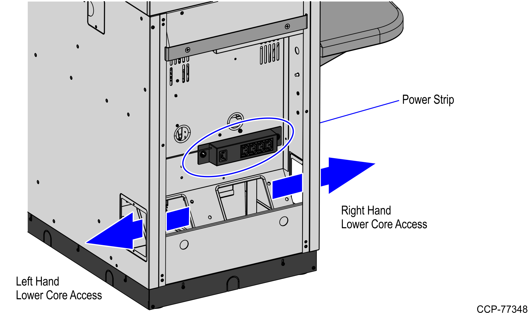
12.Ensure the E-Box can rotate freely by adjusting the position of the cable as needed. USB Power Cable should be routed through the left hand lower Core access cutout into the new Bagwell.
13.Unplug the AC Power Out and AC Power In cables from the Power Strip. AC Power In Cable will be reused in the new Bagwell. AC Power Out Cable should be routed either through the left-hand or right-hand lower Core access cutout into the new Bagwell.
Note: The Power Strip remains on the rear Core wall but not reused.
14.Finish routing the cables into the Bagwell. For more information, refer to Routing Cables .