Closing the Chassis
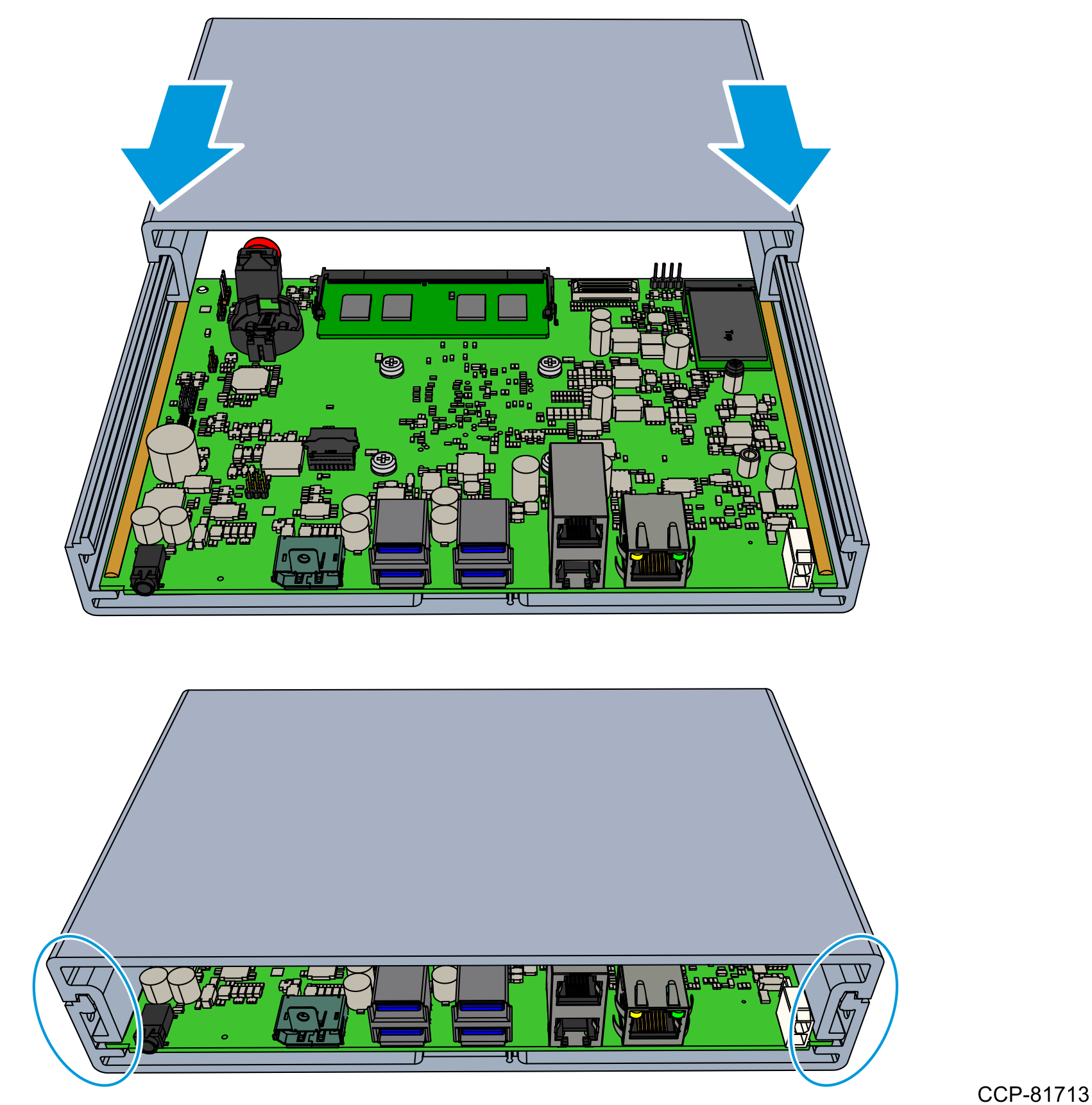
- Place the Top Extrusion into the grooves of the Bottom Extrusion, and slide the Top Extrusion until its ends are properly aligned with the Bottom Extrusion.
- Install the Back Cover.
- Attach the Plate Gasket around the top and bottom extrusions. Position the indicated portion of the Plate Gasket between the Motherboard and the Bottom Extrusion.Note
The rim of the Plate Gasket must evenly fit around the top and bottom extrusions.
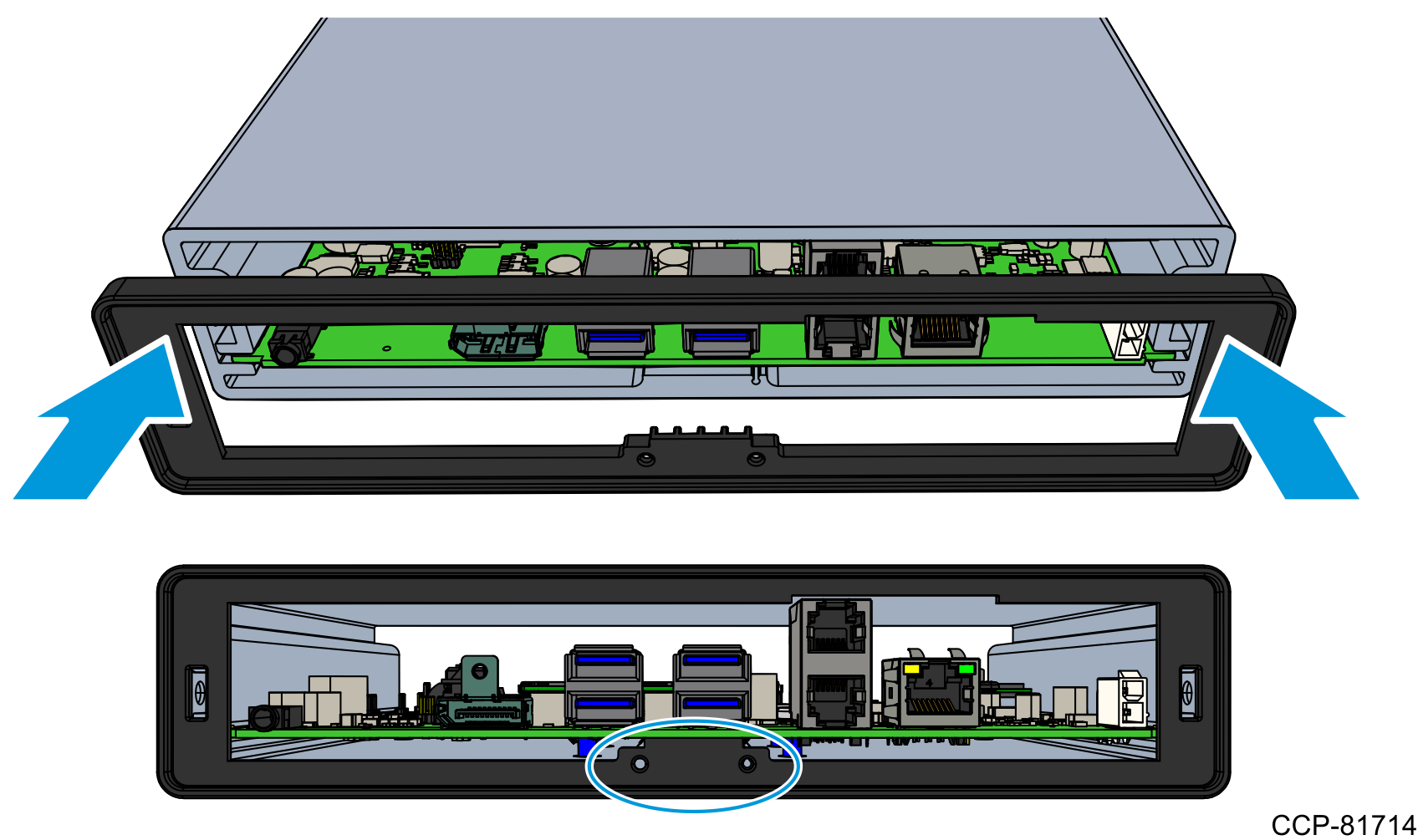
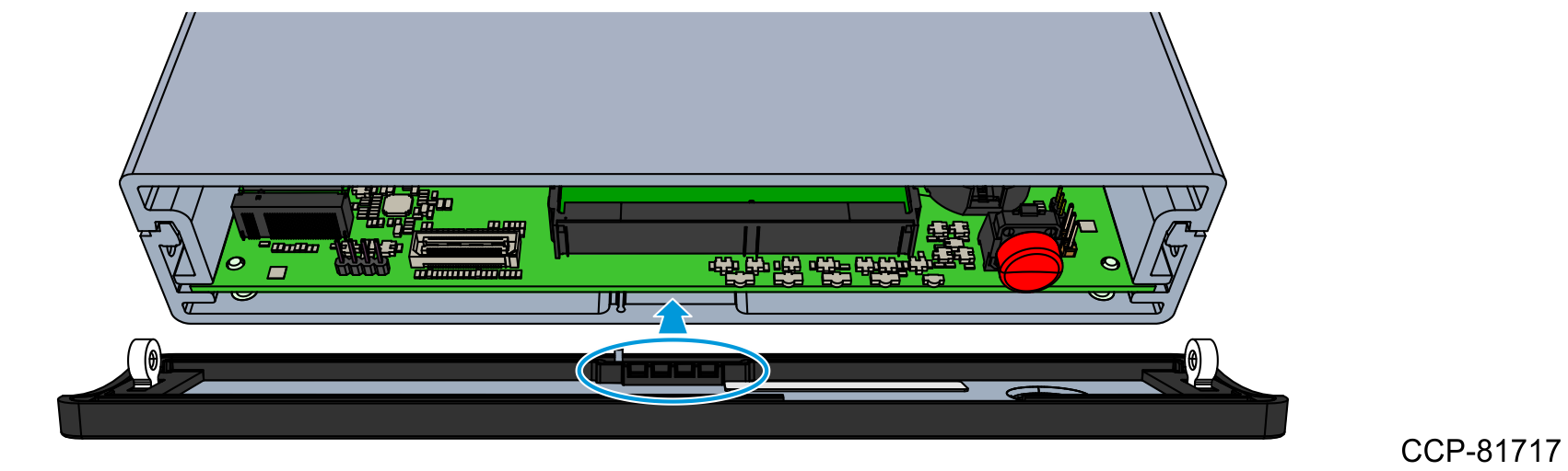
- Insert the Back Plate into the Plate Gasket.Caution
Ensure that the five grounding fingers do not go inside the connectors.
- Align the locating pin and two screw extrusions of the Back Plate with the locating features of the Plate Gasket.
- The grounding fingers (red arrows) should rest on the top or side of the connectors.
- The grounding finger (green arrow) should rest against the underside of the Top Extrusion. Gently push this grounding finger to assist in insertion.
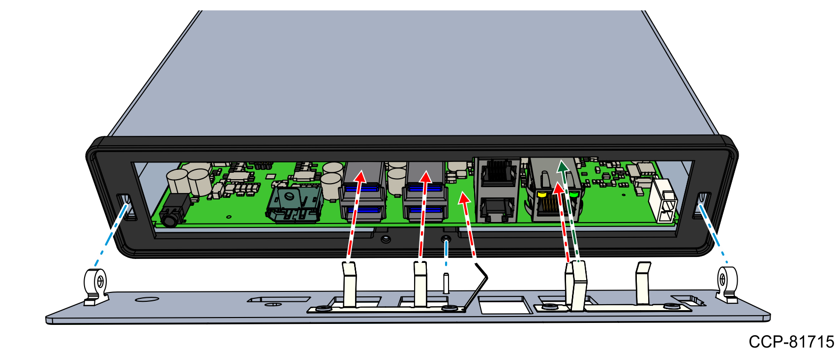
- Install the two flat head screws to secure the Back Plate and the Plate Gasket to the unit.

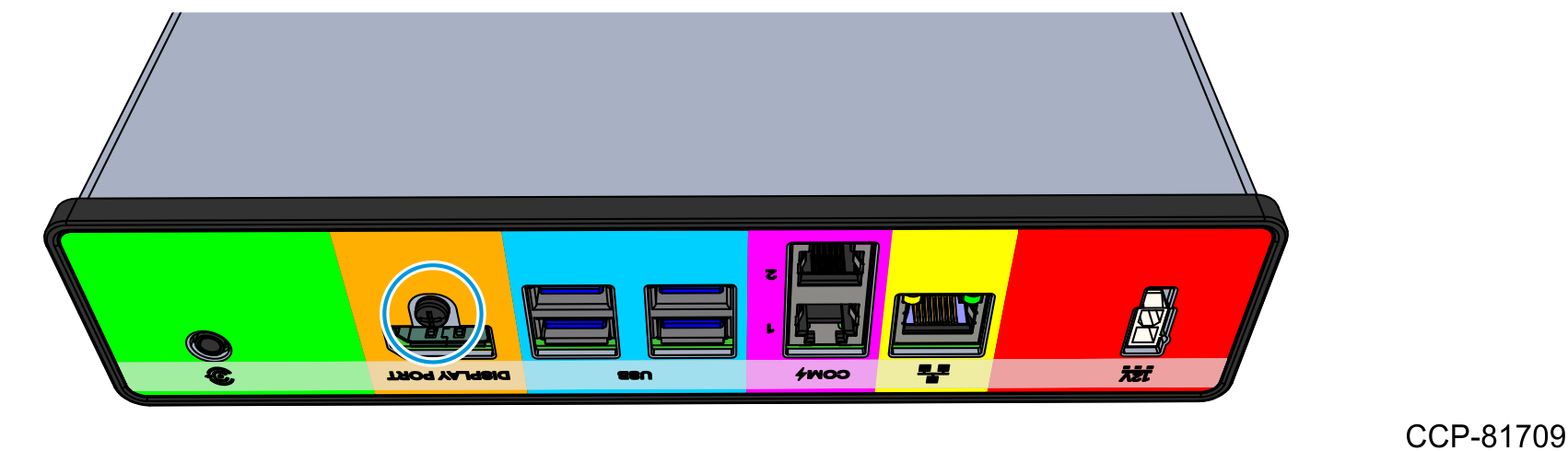
- Install the screw to secure the Back Plate to the Display Port connector.
- Attach the Plate Gasket around the top and bottom extrusions. Position the indicated portion of the Plate Gasket between the Motherboard and the Bottom Extrusion.
- Install the Front Cover.
- Align the locating pin and two screw extrusions of the Back Plate with the locating features of the top and bottom extrusions.

- Position the indicated portion of the Plate Gasket between the Motherboard and the Bottom Extrusion.Note
The rim of the Plate Gasket must evenly fit around the top and bottom extrusions.
- Install the two flat head screws to secure the Front Plate and the Plate Gasket to the unit.

- Align the locating pin and two screw extrusions of the Back Plate with the locating features of the top and bottom extrusions.
