12" Pole Mount for C730/XD10
Introduction
This kit provides the components to install a 12" pole mount to a C730 or 10.4 X–Series Display (XD10). At least one of the following Display PIDs must be ordered for this kit:
|
PID |
Description |
|---|---|
|
5934–0419–8801 |
C730 No Touch, No MSR, Black, for Pole Mount |
|
5934–0420–8801 |
C730 No Touch, No MSR, Black, with Scanner, for Pole Mount |
|
5985–1010–0003 |
X–Series 10.4" Display XB, 4m Powered USB Cable; 4m Display Port Cable; No Stand, for pole mount |
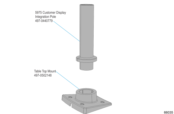
Kit Content
Installation Procedure
1.Route the cables through the Integration Pole. Secure the Integration Pole to the pole mount assembly.
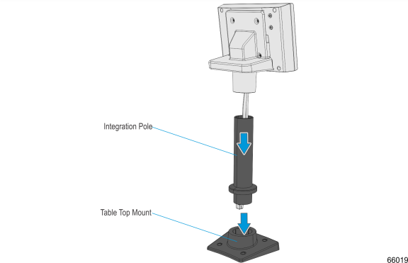
2.Route the cables through the Table Top Mount.
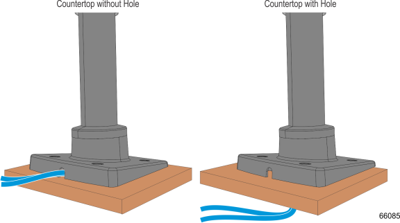
3.Secure the Table Top Mount to the countertop or integration tray with screws (4).
Note: The screws (4) are not included in the kit.
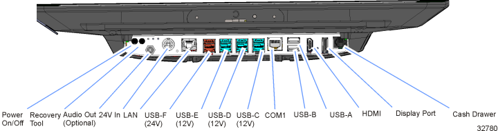
4.Route the cables through the POS stand and connect the cables to the corresponding ports on the POS terminal.
7734 Cable Routing
1.Loosen the thumbscrew and Open the CableLock Cover.
2.Route the cables under the stand and up through the CableLock Cover.
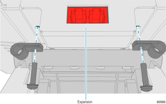
3.Route the cables into the cable clamps. Install the expansion blank plate and cable clamps (2) and secure with screws (2).
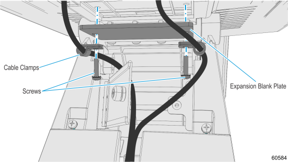
Note: If the POS includes an expansion, install the cable clamps under the expansion and secure with screws (2).
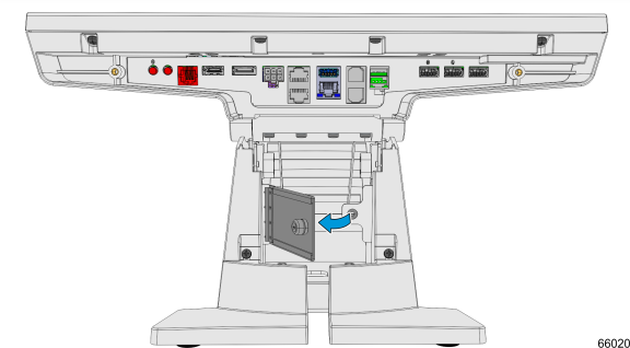
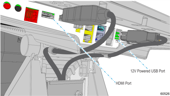
4.Connect the cables to the HDMI and 12V Powered USB ports.
5.Close and secure the CableLock Cover with the thumbscrew.
7761/7745 Cable Routing
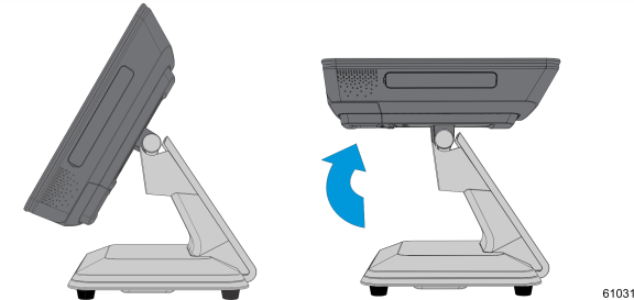
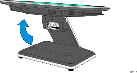
1.Pivot the display toward the back.
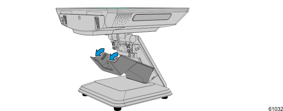
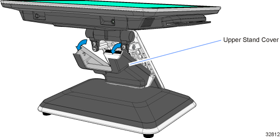
2.Remove the Upper Stand Cover by pivoting it away from the stand. The cover has a simple snap fit connection at the top.
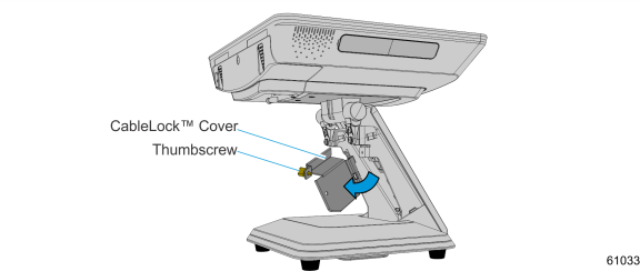
3.Open the CableLock Cover by loosening the thumbscrew.
4.Loosen the screw on the Terminal Cable Cover. To open, press down on the indentations in the Cable Cover to unlatch the cover and then pivot the cover open.
Note: Ensure that the screw is disengaged from the threads.
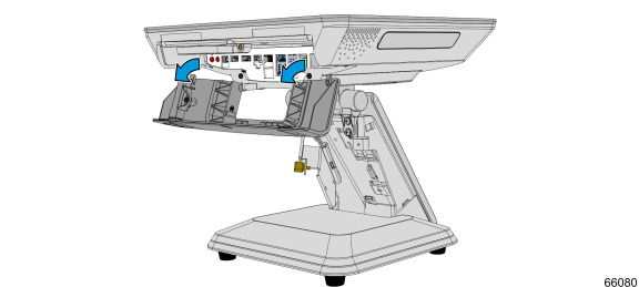
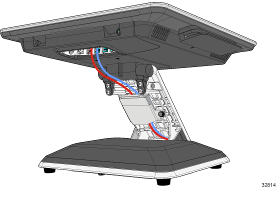
5.Route the cables up through the opening in the base of the stand.
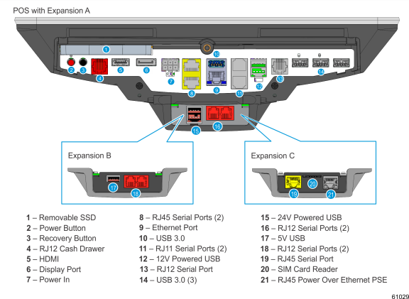
6.Connect the peripheral cables to the I/O Panel.
7.Close the CableLock Cover and secure with thumbscrew.
8. Secure the Upper Stand Cover.
9.Close the Terminal Cover and secure with screw (1).
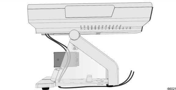
7702 Cable Routing
Cables are routed out the opening in the Cable Cover and down through the Table-Top Stand.
1.Remove the Upper Stand Cover by pivoting it away from the stand. The cover has a simple snap fit connection at the top.
2.Open the Base Cable Cover (thumb screw).
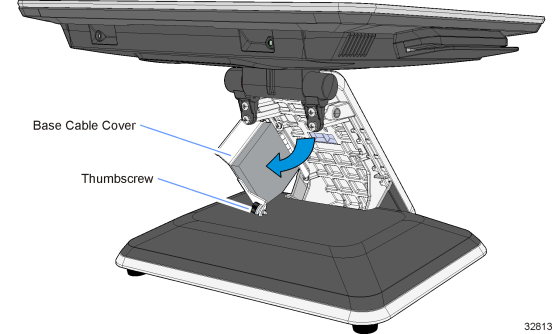
3.Route the cables down through the opening in the Stand Base.
4.Close the Base Stand Cover and secure it with the Thumb Screw.
5.Replace the Upper Stand Cover.
Connecting the 7702 Peripheral Cables
1.Unpack the terminal in the desired location.
2.Pivot the display toward the back.
3.Open the Terminal Cable Cover. Press on the indentations in the Cable Cover to unlatch the cover and then pivot the cover open.
Note: If the unit has the Cable Cover Security Bracket installed you must also loosen the two captive screws before you can open the cover.
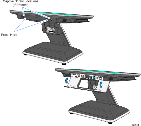
4.Connect the peripheral cables to I/O Panel.